
Page 774 - Industrial Power Engineering and Applications Handbook
P. 774
Power capacitors: behaviour, switching and improvement of power factor 231731
I-- ungrounded capacitor units i\ thus more \evere than of
Arc extinguishes and grounded units.
contacts interrwt
Charge because of (iii) Parallel switching of capacitor units
lumped capacitances
d' The amplitudes of overvoltages (TRVs) caused by a single
t ' capacitor switching, as discussed above. will diminish
-113u 5PU into when the capacitor interrupts a circuit that already
Charge
retained -f--- -1 has energized capacitor units of comparable sizes in the
IPU 3pu same system. At the instant of contact separation, the two
Voltage units, which may be charged at different potentials. will
get discharged into each other and their cumulative voltage
wave
will tend to settle at an intermediate value that will depend
- upon the size ofthe capacitors being switched. The larger
the line banks (already charged capacitors). the lower
will
!
I
;.: be the amplitude of the TRV of the combined units.
Summary of overvoltages (on HT capacitor
5pu switchings)
4PU I
1 Switching overvoltages is generally a phenomenon
of HT circuits.
2 The choice of the type of capacitor connections will
largely depend upon the system. its fault level and
112 - the presence of a communication system in the
& 112 vicinity (as a result of harmonic effects and inductive
cycle cycle interferences). Different electricity companies may
Current wave
(90" leading) ! ' , I Arc extinqutshes and adopt to different practices of capacitor connections
and their switchings, depending upon these Factors.
A more detailed study on this subject (harmonics
and inductive interferences) is beyond the scope of
this handbook, but these effects are discussed briefly
in Section 23.5.2. Various papers written on the
subject and a study of existing systems and the normal
interruption restrike restrike practices to deal with these effects and interferences
are available and may be referred to for more details.
Tme See the further reading at the end of this chapter.
Overvoltages, as developed on different grounding
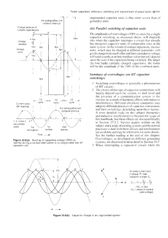
Figure 23.6(a) Build up of capacitive voltage (TRV) on systems, are discussed in more detail in Section 20.2.
restrike during a contact interruption in an ungrounded star HT
capacitor unit 3 When interrupting a capacitive circuit while the
At every current zero
in phase 'R' total
capacitor charge 'Cc',
--
- 2 2
C,=V,+G+G
R
1 [ V, =2Vmor2pu
= phase to neutral
peak voltage]
Y
Figure 23.6(b) Capacitor charge in an ungrounded system