
Page 772 - Industrial Power Engineering and Applications Handbook
P. 772
Power capacitors: behaviour, switching and improvement of power factor 23/729
Switching overvoltages
Harmonic effects and inductive interferences and
Excessive charging currents.
These aspects are discussed briefly below.
23.5.1 Switching overvoltages (surges)
This phenomenon is generally associated with an HT
system. We have discussed in Section 17.7 the subject of
switching surges as related to an inductive circuit.
Switching phenomenon in a capacitive circuit is equally
important, and a little more complex. It therefore requires
more careful handling of this device. Although the
switching behaviour of a capacitor circuit is almost a
replica of an inductive switching, its current leading the
applied voltage by 90" results in more complex behaviour
than an inductive circuit during a switching operation. C1
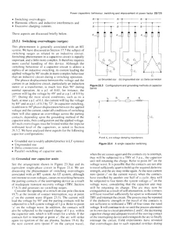
The phasor displacement between the voltage and the (a) Grounded star (b) Ungrounded star (c) Delta connection
current in an inductive circuit, particularly an induction
Figure 23.3 Configurations and grounding methods of capacitor
motor or a transformer, is much less than 90" during banks
normal operation. At a p.f. of 0.65, for instance, the
currcnt will lag the voltage by 49" and at a p.f. of 0.9 by
25". During the most severe conditions, such as on a
fault, at near a p.f. of 0. I, the current will lag the voltage
by 84" and at a p.f. of 0.3 by 72". In capacitor switching,
in addition to 90" phasor displacement between the applied
voltage and the current, under all conditions of switching 1
there will also appear an overvoltage across the parting
contacts, depending upon the grounding method of the 7 c1
capacitor units, their configuration and the applied voltage.
All such overvoltages must be limited within the impulse
withstand level of the capacitors, as noted in Section
26.32. We have analysed thete aspects for the following
capacitor configurations:
Rand X, are voltage damping impedances
Grounded star (a widely adopted practice in LT systems)
Ungrounded star Figure 23.4 A single capacitor switching
Delta connections and
Parallel switching of capacitor units.
when the arc ceases again and the contacts try to interrupt,
(i) Grounded star capacitor units they will be subjected to a TRV of 3 P.u., the capacitor
unit still retaining the charge. Refer to point bb" on the
See the arrangement shown in Figure 23.3(a) and its voltage wave. It is possible that the contacts are not able
equivalent single-phase circuit in Figure 23.4. We are to travel sufficiently apart to build up the required dielectric
discussing the phenomenon of switching overvoltages strength, and the arc may strike again. At the next current
associated with an HT system. An LT system, although zero (point c' on the current wave), when the contacts
not immune to over-voltages, causes no restriking between have travelled by another one half of a cycle, they will
the parting contacts of the interrupting device as a result be subjected to four times the system voltage CC" on the
of inadequate transient recovery voltage (TRV; Section voltage wave, considering that the capacitor unit may
17.6.2) and generates no switching surges. still be retaining its charge. The arc may now be
Consider the opening of a switch on one pole (Section extinguished as a result of self-attenuation, as the contacts
19.7) at the instant of contact interruption, say at point will have travelled sufficiently far apart to withstand the
11' on the current wave (Figure 23.5). The current will TRV and interrupt the circuit. The process may be repeated
lead the voltagc by 90" and the parting contacts will be if the dielectric strength or the travel of the contacts is
subjected to a full system voltage of I p.u. Refer to point not sufficient to withstand a TRV of four times the rated
'a' on the voltage wave. In addition, the contacts will voltage. It will continue to do so until the process attenuates
also be subjected to the trapped charge of 1 p.u. within on its own due to circuit parameters Land C, the decreasing
the capacitor unit, which it will retain for a while. If the capacitor charge and adequate travel of the moving contact
contacts fail to interrupt at point a', the arc will strike of the interrupting device and extinguish the arc to finally
again (re-ignition of the arc plasma, Section 19.4). By interrupt the circuit. Field experiments have revealed
the next current zero (point h' on the current wave), that overvoltages due to such repeated restrikes during