
Page 70 - Injection Molding Advanced Troubleshooting Guide
P. 70
54 7 Venting
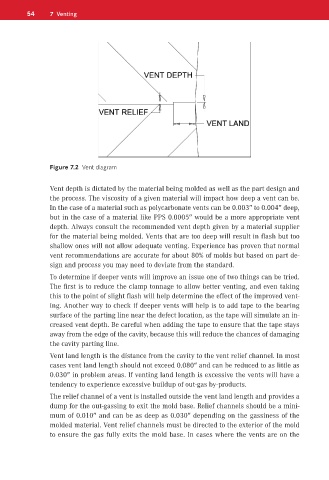
Figure 7.2 Vent diagram
Vent depth is dictated by the material being molded as well as the part design and
the process. The viscosity of a given material will impact how deep a vent can be.
In the case of a material such as polycarbonate vents can be 0.003″ to 0.004″ deep,
but in the case of a material like PPS 0.0005″ would be a more appropriate vent
depth. Always consult the recommended vent depth given by a material supplier
for the material being molded. Vents that are too deep will result in flash but too
shallow ones will not allow adequate venting. Experience has proven that normal
vent recommendations are accurate for about 80% of molds but based on part de-
sign and process you may need to deviate from the standard.
To determine if deeper vents will improve an issue one of two things can be tried.
The first is to reduce the clamp tonnage to allow better venting, and even taking
this to the point of slight flash will help determine the effect of the improved vent-
ing. Another way to check if deeper vents will help is to add tape to the bearing
surface of the parting line near the defect location, as the tape will simulate an in-
creased vent depth. Be careful when adding the tape to ensure that the tape stays
away from the edge of the cavity, because this will reduce the chances of damaging
the cavity parting line.
Vent land length is the distance from the cavity to the vent relief channel. In most
cases vent land length should not exceed 0.080″ and can be reduced to as little as
0.030″ in problem areas. If venting land length is excessive the vents will have a
tendency to experience excessive buildup of out-gas by-products.
The relief channel of a vent is installed outside the vent land length and provides a
dump for the out-gassing to exit the mold base. Relief channels should be a mini-
mum of 0.010″ and can be as deep as 0.030″ depending on the gassiness of the
molded material. Vent relief channels must be directed to the exterior of the mold
to ensure the gas fully exits the mold base. In cases where the vents are on the