
Page 171 - Solutions Manual to accompany Electric Machinery Fundamentals
P. 171
jX R jX 1 R j X X M
Z M 1 1 1
TH R X j X R X j X
1 1 M 1 1 M
RX X RX X RX M 2 j R X 2 X X 2 X X M 2
Z 1 1 M 1 1 M 1 1 M 1 M 1
TH 2 2
R 1 1 X M X
RX 2 R X 2 X X 2 X X 2
Z R jX 1 M j 1 M 1 M 1 M
TH TH TH 2 2 2 2
R 1 1 X M X R 1 1 X M X
RX 2 2 2
The Thevenin resistance is R TH 1 M . If X M R , then R 1 2 X 1 X M X 1 X M ,
1
R 1 2 1 X M X 2
so
X 2
R R 1 M
TH X X M
1
R X 2 X X 2 X X 2
The Thevenin reactance is X TH 1 M 1 M 2 1 M .
R 1 2 1 X M X
2
2
2
If X M R and X M X then X X M 2 R X X X and X 1 X M 2 X M 2 R , so
1
M
1
1
1
M
1
1
XX 2
X 1 M X
TH
X M 2 1
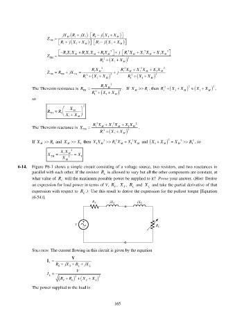
6-14. Figure P6-1 shows a simple circuit consisting of a voltage source, two resistors, and two reactances in
parallel with each other. If the resistor R L is allowed to vary but all the other components are constant, at
what value of R L will the maximum possible power be supplied to it? Prove your answer. (Hint: Derive
an expression for load power in terms of V, R S , X S , R L and X L and take the partial derivative of that
expression with respect to R L .) Use this result to derive the expression for the pullout torque [Equation
(6-54)].
SOLUTION The current flowing in this circuit is given by the equation
V
I
R S jX S R L jX L
L
V
I
L
S L R 2 R X X L S 2
The power supplied to the load is
165