Page 167 - Solutions Manual to accompany Electric Machinery Fundamentals
P. 167

I A
                                         R 1      jX 1         jX 2       R 2


                                  +                           j0.175 ?   0.07 ?
                                        0.10 ?  j0.175 ?
                                                                                        1   s
                                                   j8.33 ?  jX M                    R      
                                 V ?                                                  2  s  

                                                                                      1.33 ?
                                  -

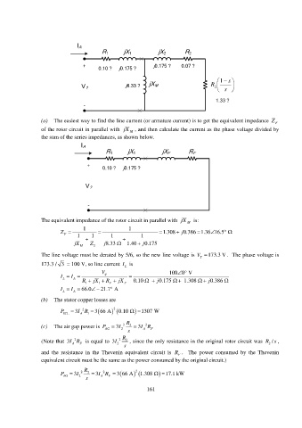
                 (a)  The easiest way to find the line current (or armature current) is to get the equivalent impedance  Z F
                 of the rotor circuit in parallel with  jX  M  , and then calculate the current as the phase voltage divided by
                 the sum of the series impedances, as shown below.

                                 I A
                                           R 1     jX 1          jX F      R F

                                   +
                                         0.10 ?   j0.175 ?


                                   V ?


                                    -

                 The equivalent impedance of the rotor circuit in parallel with  jX  M   is:
                                  1                 1
                         Z   F  1   1      1           1        1.308   j 0.386 1.36 16.5        

                              jX M    Z 2  j 8.33     1.40   j 0.175

                 The line voltage must be derated by 5/6, so the new line voltage is V  173.3 V .  The phase voltage is
                                                                                T
                 173.3 / 3  = 100 V, so line current  I L  is
                                         V                          100 0  V
                                                                       
                         I   L  I   A            
                                 R   1  jX   1  R   F  jX F  0.10       j 0.175      1.308     j 0.386 
                                             
                         I   L  I   A  66.0    21.7 A
                 (b)  The stator copper losses are

                         P SCL    3I A 2  1   R    3 66 A  2    0.10     1307 W
                                                   R
                                                          2
                 (c)  The air gap power is  P    3I  2  2    3I R
                                                 2
                                          AG
                                                   s      A  F
                                                 R
                              2
                                                                                                            /
                 (Note that 3IR    is equal to  3I  2  2  , since the only resistance in the original rotor circuit was  R s ,
                                F
                              A
                                               2
                                                  s                                                        2
                 and the resistance in the Thevenin equivalent circuit  is  R .  The power consumed by the Thevenin
                                                                       F
                 equivalent circuit must be the same as the power consumed by the original circuit.)
                                  R                   2
                         P     3I  2  2    3I  2   R    3 66 A    1.308        17.1 kW
                          AG
                                2
                                   s     A  F
                                                           161
   162   163   164   165   166   167   168   169   170   171   172