Page 182 - Solutions Manual to accompany Electric Machinery Fundamentals
P. 182

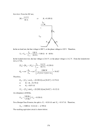
SOLUTION  From the DC test,
                              13.5 V
                         2R                         R  0.105 
                           1
                               64 A                    1
                                                     I DC


                                                   +

                                                                  R
                                                                   1

                                                 V
                                                  DC

                                                          R 1         R 1

                                                   -

                 In the no-load test, the line voltage is 208 V, so the phase voltage is 120 V.  Therefore,
                                   V     120 V
                         X   1  X M           5.00     @   60 Hz
                                                      
                                   I A ,nl  24.0 A
                 In the locked-rotor test, the line voltage is 24.6 V, so the phase voltage is 14.2 V.  From the locked-rotor
                 test at 15 Hz,
                                             V     14.2 V
                         Z     R    jX              0.220 
                           LR
                                 LR
                                       LR
                                            I A ,LR  64.5 A
                                   P               2200 W       
                             cos   1  LR    cos     1         36.82
                          LR
                                   S                          
                                    LR                  3 24.6 V 64.5 A    
                 Therefore,
                         R LR    Z LR  LR      cos  0.220   cos 36.82   0.176   
                               R   1  R   2  0.176  
                               R   2  0.071  

                                                                        
                         X   LR    Z  LR  s  LR     in  0.2202   sin 36.82     0.132
                 At a frequency of 60 Hz,
                                 60 Hz
                         X LR        15 Hz     X  LR    0.528 

                 For a Design Class B motor, the split is  X  0.211   and  X   0.317  .  Therefore,
                                                                       2
                                                      1
                         X     5.000     0.211     4.789 
                           M
                 The resulting equivalent circuit is shown below:


                                                           176
   177   178   179   180   181   182   183   184   185   186   187