Page 198 - Solutions Manual to accompany Electric Machinery Fundamentals
P. 198

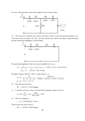
SOLUTION  The equivalent circuit of this induction motor is shown below:

                               I A
                                         R 1      jX 1         jX 2       R 2

                                  +                           j0.386 ?  0.037 ?
                                       0.058 ?  j0.320 ?
                                                                                           s
                                                                                        1
                                                   j9.24 ?  jX M                    R      
                                                                                        s  
                                 V ?                                                  2
                                                                                      3.663 ?
                                  -

                 (a)  The easiest way to find the line current (or armature current) is to get the equivalent impedance  Z F
                 of the rotor circuit in parallel with  jX  M  , and then calculate the current as the phase voltage divided by
                 the sum of the series impedances, as shown below.

                                 I A
                                           R 1     jX 1          jX F      R F

                                   +     0.058 ?  j0.320 ?


                                   V ?


                                    -


                 The equivalent impedance of the rotor circuit in parallel with  jX  is:
                                                                           M
                                  1                 1
                         Z   F  1   1      1           1        2.970   j 1.512 3.333 27.0       
                                                                               
                              jX M    Z 2  j 9.24     3.70   j 0.386


                 The phase voltage is 460/ 3  = 266 V, so line current  I L   is
                                                                       
                                         V                         266 0  V
                            I   I                
                          L   A
                                 R   1  jX   1  R   F  jX F  0.058       j 0.32      2.97     j 1.512 
                                             
                            I   I  75.2     31.2  A
                          L   A
                 (b)  The stator power factor is
                         PF   cos 31.2   0.855  lagging

                 (c)  To find the rotor power factor, we must find the impedance angle of the rotor

                            tan   1  X 2    tan   1  0.386    5.96
                          R
                                  R  / s      0.037 / 0.01
                                   2
                 (d)  The rotor frequency is
                                       
                         f       sf   0.01 60 Hz     0.6 Hz
                          r    s
                 Therefore the rotor power factor is
                         PF   R  cos5.96    0.995  lagging

                                                           192
   193   194   195   196   197   198   199   200   201   202   203