
Page 200 - Solutions Manual to accompany Electric Machinery Fundamentals
P. 200
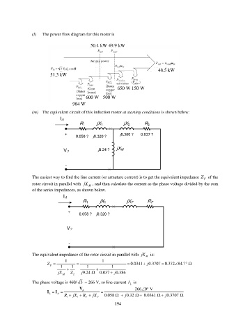
(l) The power flow diagram for this motor is
50.4 kW 49.9 kW
48.5 kW
51.3 kW
650 W 150 W
600 W 500 W
984 W
(m) The equivalent circuit of this induction motor at starting conditions is shown below:
I A
R 1 jX 1 jX 2 R 2
+ j0.386 ? 0.037 ?
0.058 ? j0.320 ?
j9.24 ? jX M
V ?
-
The easiest way to find the line current (or armature current) is to get the equivalent impedance Z F of the
rotor circuit in parallel with jX M , and then calculate the current as the phase voltage divided by the sum
of the series impedances, as shown below.
I A
R 1 jX 1 jX F R F
+
0.058 ? j0.320 ?
V ?
-
The equivalent impedance of the rotor circuit in parallel with jX is:
M
1 1
Z F 1 1 1 1 0.0341 j 0.3707 0.372 84.7
jX M Z 2 j 9.24 0.037 j 0.386
The phase voltage is 460/ 3 = 266 V, so line current I L is
V 266 0 V
I I
R 1 jX 1 R F jX F 0.058 j 0.32 0.0341 j 0.3707
L A
194