
Page 204 - Solutions Manual to accompany Electric Machinery Fundamentals
P. 204
n n 1800 1764
s sync m 1.98
n sync 1800
(e) The frequency of the rotor after plugging is f sf 1.98 60 Hz 118.8 Hz
r e
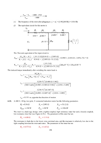
(f) The equivalent circuit for this motor is
I A
R 1 jX 1 jX 2 R 2
+ 0.54 ? j2.093 ? j3.209 ? 0.488 ?
s
1
j51.12 ? jX M R
V ? 2
s
-
The Thevenin equivalent of the input circuit is:
jX R jX 51.12j 0.54 j 2.093
Z M 1 1 0.4983 j 2.016 2.076 76.1
TH
R 1 1 M j X 0.54 j X 51.12 2.093
jX 51.2 j
V M V 266 0 V 256 0.58 V
TH
R 1 1 X M j X 0.54 j 51.2 2.093
The induced torque immediately after switching the stator leads is
2
/
3VR s
ind TH 2
sync TH 2 / 2 R s X TH X 2 R 2
3 256 V 2 0.488 /1.962
ind
188.5 rad/s 0.4983 0.488 2 /1.962 2.016 3.209 2
3256 V 2 0.2 487
ind
188.5 rad/s 0.4983 0.2487 2 2.016 3.209 2
ind 9.3 N m, opposite the direction of motion
6-32. A 460-V, 10 hp, two-pole, Y-connected induction motor has the following parameters
R = 0.54 X 1 = 2.093 X M = 51.12
1
P F&W = 150 W P misc = 50 W P core = 150 kW
The rotor is a dual-cage design, with a tightly-coupled, high resistance outer bar and a loosely-coupled,
low resistance inner bar (see Figure 6-25c). The parameters of the outer bar are
R = 4.80 X = 3.75
2o
2o
The resistance is high due to the lower cross sectional area, and the reactance is relatively low due to the
tight coupling between the rotor and stator. The parameters of the inner bar are
R = 0.573 X = 4.65
2i
2i
198