Page 325 - Solutions Manual to accompany Electric Machinery Fundamentals
P. 325

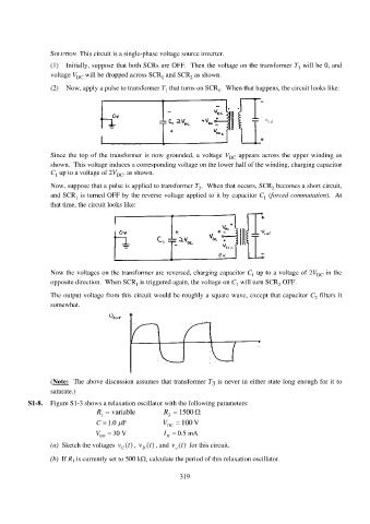
SOLUTION  This circuit is a single-phase voltage source inverter.
                 (1)  Initially, suppose that both SCRs are OFF.  Then the voltage on the transformer T  will be 0, and
                                                                                                 3
                 voltage V DC  will be dropped across SCR  and SCR  as shown.
                                                     1
                                                              2
                 (2)  Now, apply a pulse to transformer T  that turns on SCR .  When that happens, the circuit looks like:
                                                                       1
                                                      1


                 Since the top of the transformer is now grounded, a voltage V DC  appears across the upper winding as
                 shown.  This voltage induces a corresponding voltage on the lower half of the winding, charging capacitor
                 C  up to a voltage of 2V DC , as shown.
                   1
                 Now, suppose that a pulse is applied to transformer T .  When that occurs, SCR  becomes a short circuit,
                                                                                        2
                                                                 2
                 and SCR  is turned OFF by the reverse voltage applied to it by capacitor C  (forced commutation).  At
                                                                                      1
                         1
                 that time, the circuit looks like:


                 Now the voltages on the transformer are reversed, charging capacitor C  up to a voltage of 2V DC  in the
                                                                                  1
                 opposite direction.  When SCR  is triggered again, the voltage on C  will turn SCR  OFF.
                                             1
                                                                                           2
                                                                             1
                 The output voltage from this circuit would be roughly a square wave, except that capacitor C  filters it
                                                                                                      2
                 somewhat.


                 (Note:  The above discussion assumes that transformer T  is never in either state long enough for it to
                                                                     3
                 saturate.)
          S1-8.  Figure S1-3 shows a relaxation oscillator with the following parameters:
                                R  variable          R 2   1500  
                                 1
                                C  1.0 F            V DC   100 V
                                       
                                V BO    30 V         I   0.5 mA
                                                       H
                 (a)  Sketch the voltages v t() vt() , and vt()  for this circuit.
                                            ,
                                                         o
                                               D
                                        C
                 (b)  If R 1 is currently set to 500 k, calculate the period of this relaxation oscillator.
                                                           319
   320   321   322   323   324   325   326   327   328   329   330