
Page 324 - Solutions Manual to accompany Electric Machinery Fundamentals
P. 324
Note: This problem could also have been solved using Laplace Transforms, if desired.
(b) The rms voltage applied to the load is
/
1
2
t
V v () t 2 dt V 2 sin dt
rms
T M
V M 2 1 1 /
V rms t sin2 t
4
2
V M 2 1 1
V sin2 sin2
rms 2 4
V rms V M 0.3284 0.573 V M 97.1 V
S1-6. One problem with the circuit shown in Figure S1-1 is that it is very sensitive to variations in the input
t
voltage v () . For example, suppose the peak value of the input voltage were to decrease. Then the
ac
time that it takes capacitor C 1 to charge up to the breakover voltage of the DIAC will increase, and the
SCR will be triggered later in each half cycle. Therefore, the rms voltage supplied to the load will be
reduced both by the lower peak voltage and by the later firing. This same effect happens in the opposite
t
direction if v () increases. How could this circuit be modified to reduce its sensitivity to variations in
ac
input voltage?
SOLUTION If the voltage charging the capacitor could be made constant or nearly so, then the feedback
effect would be stopped and the circuit would be less sensitive to voltage variations. A common way to
do this is to use a zener diode that fires at a voltage greater than V BO for the DIAC across the RC charging
circuit. This diode holds the voltage across the RC circuit constant, so that the capacitor charging time is
not much affected by changes in the power supply voltage.
R
v
C
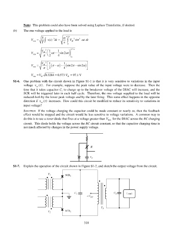
S1-7. Explain the operation of the circuit shown in Figure S1-2, and sketch the output voltage from the circuit.
318