
Page 319 - Solutions Manual to accompany Electric Machinery Fundamentals
P. 319
disp(string);
When this program is executed, the results are
» test_fullwave3
The ripple is 4.2017%.
This answer agrees with the analytical solution above.
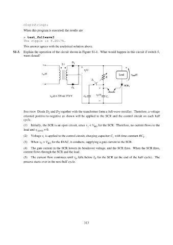
S1-3. Explain the operation of the circuit shown in Figure S1-1. What would happen in this circuit if switch S 1
were closed?
SOLUTION Diode D and D together with the transformer form a full-wave rectifier. Therefore, a voltage
1
2
oriented positive-to-negative as shown will be applied to the SCR and the control circuit on each half
cycle.
(1) Initially, the SCR is an open circuit, since v < V BO for the SCR. Therefore, no current flows to the
1
load and v LOAD = 0.
(2) Voltage v is applied to the control circuit, charging capacitor C with time constant RC .
1
1
1
(3) When v > V BO for the DIAC, it conducts, supplying a gate current to the SCR.
C
(4) The gate current in the SCR lowers its breakover voltage, and the SCR fires. When the SCR fires,
current flows through the SCR and the load.
(5) The current flow continues until i falls below I for the SCR (at the end of the half cycle). The
D
H
process starts over in the next half cycle.
313