
Page 321 - Solutions Manual to accompany Electric Machinery Fundamentals
P. 321
1 1
V V 1 V 0.318 169.5 V 54 V
ave M M
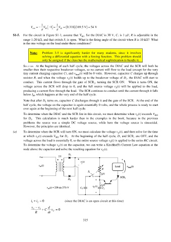
S1-5. For the circuit in Figure S1-1, assume that V BO for the DIAC is 30 V, C 1 is 1 F, R is adjustable in the
range 1-20 k, and that switch S 1 is open. What is the firing angle of the circuit when R is 10 k? What
is the rms voltage on the load under these conditions?
Note: Problem 3-5 is significantly harder for many students, since it involves
solving a differential equation with a forcing function. This problem should
only be assigned if the class has the mathematical sophistication to handle it.
SOLUTION At the beginning of each half cycle, the voltages across the DIAC and the SCR will both be
smaller then their respective breakover voltages, so no current will flow to the load (except for the very
tiny current charging capacitor C), and v load (t) will be 0 volts. However, capacitor C charges up through
resistor R, and when the voltage v (t) builds up to the breakover voltage of D , the DIAC will start to
C
1
conduct. This current flows through the gate of SCR , turning the SCR ON. When it turns ON, the
1
voltage across the SCR will drop to 0, and the full source voltage v (t) will be applied to the load,
S
producing a current flow through the load. The SCR continues to conduct until the current through it falls
below I , which happens at the very end of the half cycle.
H
Note that after D turns on, capacitor C discharges through it and the gate of the SCR. At the end of the
1
half cycle, the voltage on the capacitor is again essentially 0 volts, and the whole process is ready to start
over again at the beginning of the next half cycle.
To determine when the DIAC and the SCR fire in this circuit, we must determine when v (t) exceeds V BO
C
for D . This calculation is much harder than in the examples in the book, because in the previous
1
problems the source was a simple DC voltage source, while here the voltage source is sinusoidal.
However, the principles are identical.
(a) To determine when the SCR will turn ON, we must calculate the voltage v (t), and then solve for the time
C
at which v (t) exceeds V BO for D . At the beginning of the half cycle, D and SCR are OFF, and the
C
1
1
1
voltage across the load is essentially 0, so the entire source voltage v (t) is applied to the series RC circuit.
S
To determine the voltage v (t) on the capacitor, we can write a Kirchhoff's Current Law equation at the
C
node above the capacitor and solve the resulting equation for v (t).
C
i 1 i 2 0 (since the DIAC is an open circuit at this time)
v C v 1 C d v 0
R dt C
315