Page 50 - Solutions Manual to accompany Electric Machinery Fundamentals
P. 50

SOLUTION
                 (a)  The transformer supplies a load of 80 MVA at 0.8 PF lagging.  Therefore, the secondary line current
                 of the transformer is

                       I LS    S    80,000,000 VA    402 A
                               LS      3V     V  3 115,000
                 The base apparent power is  S base   100 MVA  ,  and the base line voltage on the secondary side is
                 V LS ,base   115 kV , so the base value of the secondary line current is


                       I LS ,base    S base    100,000,000 VA    502 A
                                3V LS ,base         V  3 115,000

                 so the per-unit secondary current is
                              I      402 A
                             I  LS           1  cos  0.8   0.8    36.87
                        LS ,pu
                              I LS ,pu  502 A
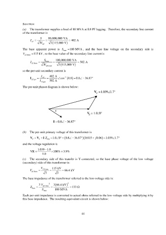
                 The per-unit phasor diagram is shown below:
                                                                     V P V 1.039 1.7 P    


                                        
                                                                V  = 1.00°
                                                                 S
                                             
                                                      
                                          I  0.8  I = 0.8-31.8°
                                                 36.87

                 (b)  The per-unit primary voltage of this transformer is

                           V   V    I  1.0 0       Z    36.87   0.8  0.015   j 0.06  1.039 1.7    
                        P    S     EQ
                 and the voltage regulation is
                                 
                            1.039 1.0
                       VR              100% 3.9%
                                             
                               1.0
                 (c)  The secondary side of this transfer is Y-connected, so the base phase voltage of the low voltage
                 (secondary) side of this transformer is:
                              V       115 kV
                      V  S ,base    LS ,base      66.4 kV
                                 3        3
                 The base impedance of the transformer referred to the low-voltage side is:

                             3 V    2             3 66.4 kV  2
                       Z        S      ,base     133 
                        base
                               S        100 MVA
                                base
                 Each per-unit impedance is converted to actual ohms referred to the low-voltage side by multiplying it by
                 this base impedance.  The resulting equivalent circuit is shown below:


                                                           44
   45   46   47   48   49   50   51   52   53   54   55