
Page 53 - Solutions Manual to accompany Electric Machinery Fundamentals
P. 53
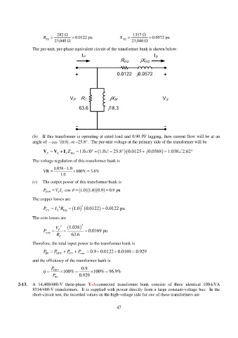
282 1317
R 0.0122 pu X 0.0572 pu
EQ EQ
23,040 23,040
The per-unit, per-phase equivalent circuit of the transformer bank is shown below:
I P I S
jX EQ
R EQ
+ 0.0122 j0.0572 +
V P R C jX M V S
63.6 j18.3
- -
(b) If this transformer is operating at rated load and 0.90 PF lagging, then current flow will be at an
angle of cos 1 9 . 0 , or –25.8. The per-unit voltage at the primary side of the transformer will be
V V I Z 1.0 0 25.8 1.0 0.0125 j 0.0588 1.038 2.62
P S S EQ
The voltage regulation of this transformer bank is
1.038 1.0
VR 100% 3.8%
1.0
(c) The output power of this transformer bank is
P OUT V I cos 1.0 1.0 0.9 0.9 pu
SS
The copper losses are
P I R 1.0 2 0.0122 0.0122 pu
2
CU S EQ
The core losses are
2 V 1.038 2
P P 0.0169 pu
core
R 63.6
C
Therefore, the total input power to the transformer bank is
P IN P OUT P CU P core 0.9 0.0122 0.0169 0.929
and the efficiency of the transformer bank is
P 0.9
OUT 100% 100% 96.9%
P IN 0.929
2-13. A 14,400/480-V three-phase Y--connected transformer bank consists of three identical 100-kVA
8314/480-V transformers. It is supplied with power directly from a large constant-voltage bus. In the
short-circuit test, the recorded values on the high-voltage side for one of these transformers are
47