
Page 56 - Solutions Manual to accompany Electric Machinery Fundamentals
P. 56
% to the primary side for each current and
% power factor.
aVSP = VPP - (Req.*I + j.*Xeq.*I);
% Refer the secondary phase voltages back to
% the secondary side using the turns ratio.
% Because this is a delta-connected secondary,
% this is also the line voltage.
VSP = aVSP * (480/8314);
% Plot the secondary voltage versus load
plot(amps,abs(VSP(1,:)),'b-','LineWidth',2.0);
hold on;
plot(amps,abs(VSP(2,:)),'k--','LineWidth',2.0);
plot(amps,abs(VSP(3,:)),'r-.','LineWidth',2.0);
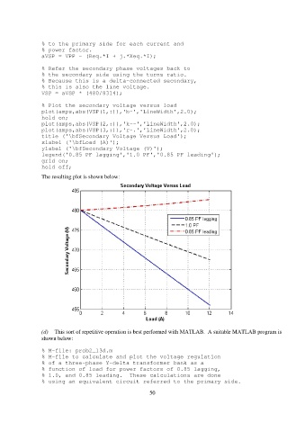
title ('\bfSecondary Voltage Versus Load');
xlabel ('\bfLoad (A)');
ylabel ('\bfSecondary Voltage (V)');
legend('0.85 PF lagging','1.0 PF','0.85 PF leading');
grid on;
hold off;
The resulting plot is shown below:
(d) This sort of repetitive operation is best performed with MATLAB. A suitable MATLAB program is
shown below:
% M-file: prob2_13d.m
% M-file to calculate and plot the voltage regulation
% of a three-phase Y-delta transformer bank as a
% function of load for power factors of 0.85 lagging,
% 1.0, and 0.85 leading. These calculations are done
% using an equivalent circuit referred to the primary side.
50