
Page 117 - Instrumentation Reference Book 3E
P. 117
102 Vibration
2.0 I
Damping
Half sine input
-pulse
Figure 6.1 6 A range of accelerometers is required to
cover the full needs of vibration measurement. Courtesy, ~ Seismometer
output responses
lnspek Supplies, New South Wales. for varying degrees
of damping
-Time
Natural period of seismometer = duration
of half sine pulse
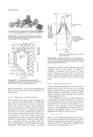
Figure 6.18 Example of response, at variousdamping
factor levels, of a seismic accelerometer to a complex forcing
input-a half-sine wave of similar period to that of the natural
resonance period of the sensor.
that depends largely on the damping and natural
frequency values of the sensor. A number of
responses are plotted, such as that in Figure
6.18, in Harris and Crede (1961), to which the
reader is referred. Generally the damping value
1 io io2 io3 io4 io5 for best all-round results is that near the critical
Frequency
value.
Figure 6.17 Useful linear operating range of an
individual seismic vibration sensor can be characterized
with this form of chart. Courtesy, McGraw-Hill. 6.3.4.3 The piezoelectric sensor
Numerous sensing methods have been devised to
pliant clamping bolt. In the case of piezosensitive measure the motion of the mass in a seismic
material use is often made of the compliance of sensor. We discuss here the most commonly used
the material. method: others are described in Endevco (1980),
Harris and Crede (l96l), Herceg (l972), Norton
(1969), and Oliver (1971).
6.3.4.2 Response to complex wuvejomts Force applied to certain crystalline substances.
The response curves given relate to seismic sen- such as quartz, produces between two surfaces of
sors excited by sinusoidal signals. To predict the a suitably shaped crystal an electric charge that is
behavior of a certain sensor, such as an accelero- proportional to the force. This charge is con-
meter, when used to measure other continuous tained in the internal electrical capacitance
or discrete waveforms it is first necessary to break formed by the high-dielectric material and two
down the waveform into its Fourier components. deposited conducting surfaces. The descriptive
The response, in terms of amplitude and phase, to mathematical relation for this effect is
each of these is then added to arrive at the result- q=u.F. Ks
ant response. It has been stated above that
damping can be added to extend the useful band- where q is the electrical charge generated by force
width of a seismic sensor. However, where this is F (in newtons) applied across the faces of a piezo-
done it generally increases the phase shift vari- electric device having a mechanical compliance of
ation with frequency. A signal comprising many spring rate K,(mN-') and a more complex mater-
frequencies will, therefore, produce an output ial constant u (of dimensions C m-').