
Page 115 - Instrumentation Reference Book 3E
P. 115
100 Vibration
nominal value of 0.5. This, however, does intro- prises a cylindrical coil vibrating inside a mag-
duce more rapidly changing phase shift error with netic field that is produced by a permanent
frequency which may be important. The lowest electromagnet. A commonly seen arrangement,
frequency of use above which the response Figure 6.15(a), is that typified by the reversible-
remains virtually flat is seen to be where the var- role moving-coil, loud-speaker movement. For
ious damping factor curves approach the this form the output voltage Vout is given by
horizontal line equal to unity ratio, to within the
allowable signal tolerance. V,,, = -Blv. lop9
Given that the chosen damping remains where B is the flux density in tesla, 1 the effective
constant and that a system does follow the length of conductor contributing in total
second-order response it is also possible to pro- flux-cutting, and B the instantaneous velocity,
vide electronic frequency compensation that can expressed in mspl, of the coil relative to the
further lower the useful frequency of operation by magnet. Given that the design ensures that the
a small amount. field is uniform in the path of the fixed conductor
Thus to directly measure displacement ampli- length the sensor can provide very linear output.
tudes with a seismic sensor it must have a natural
frequency set to be below the lowest frequency of
interest in the subject's vibration spectrum. In Cylindrical
this mode the seismic mass virtually remains sta- air-gap
tionary in space acting as a fixed reference point. c
It is also clear that the seismic sensor cannot
measure very low frequencies for it is not possible
to construct an economical system having a low
enough resonant frequency.
The curves are theoretical perfections and Fixed coaxial
would apparently indicate that the seismic sensor, permanent
magnet
in this case, will have flat response out to infinite Moving structure
coil in
frequency. This is not the case in practice for as magnetic
the frequency of vibration rises the seismic sensor Velocity field
input
structure begins to resonate at other frequencies
caused by such mechanisms as the spring vibrat-
ing in modes other than the fundamental of the Variable air-gap modulates magnetic circuit
system.
Given that the low frequency range of accel-
erometers can extend down to less than 1Hz
(see Section 6.3.4) it may often be more practical Ferro- output
to twice integrate an accelerometer signal, in magnetic
order to derive displacement amplitude, rather material (b)
than to make use of a direct-reading displacement
design of seismic sensor. /
Vibration measurement is also discussed in
Chapter 12. Magnetic
- circuit
Vibrating input
6.3.3 Velocity measurement
The prime method used to generate a direct velo-
city signal makes use of the law of electromag-
netic induction. This gives the electrical voltage e
generated as N turns of an electric coil cut mag-
netic flux $ over time t as (C)
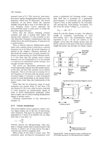
Velocity sensors are self-generating. They pro-
duce a voltage output that is proportional to the
velocity at which a set of turns moves through a Magnet moving in coil
in vibration direction
constant and uniform magnetic field.
Many forms of this kind of sensor exist. The Figure 6.15 Forms of velocitysensor. (a) Moving coil.
commonly used, moving-coil arrangement com- (b) Variable reluctance. (c) Moving permanent magnet.