
Page 112 - Instrumentation Reference Book 3E
P. 112
Sensor practice 97
used to produce known accelerations on a known
mass. In this way the forces exerted on the accel-
erometer can be determined along with the corres-
ponding output voltage or current needed to
produce transducer sensitivity constants.
Space does not permit greater explanation 'out
there are several detailed accounts of vibration
sensor calibration available in the literature-
Endevco (1980), Harris and Crede (196P), Herceg
(1972): Norton (1969), Oliver (1971), and Trampe-
Broch (1980). National and international stand-
ards are extensively listed in Bruel and Kjaer
(1981).
6.3 Sensor practice
6.3.1 Mass-spring seismic sensors
Whereas the fixed reference methods do have
some relevance in the practical measurement of
vibration the need for a convenient datum is very
often not able to be met. In the majority of vibra-
tion measurements use is made of the mass-spring,
seismic sensor system.
Given the correct spring-mass-damping com-
bination a seismic system attached to a vibrating
surface can yield displacement, velocity, or accelera-
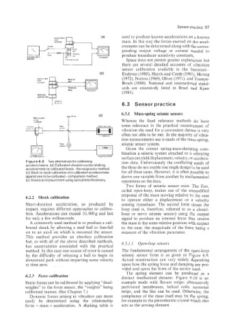
Figure 6.8 Two alternativesforcalibrating tion data. Unfortunately the conflicting needs of
accelercmeters. (a) Calibrated vibration exciter shaking the three do not enable one single design to be used
accelerometer at calibrated levels-the reciprocity method
(b) Back-to-back calibration of a calibrated accelerometer for all three cases. However, it is often possible to
against one to be calibrated-comparison method. derive one variable from another by mathematical
(c) Absolute measurement using optical interferometry. operations on the data.
Two forms of seismic sensor exist. The first.
called open-loop, makes use of the unmodified
response of the mass moving relative to the case
6.2.2 Shock calibration
to operate either a displacement or a velocity
Short-duration acceleration, as produced by sensing transducer. The second form closes the
impact, requires different approaches to calibra- loop (and is, therefore. referred to as a closed-
tion. Accelerations can exceed 10,000 g and last loop or servo seismic sensor) using the output
for only a few milliseconds. signal to produce an internal force that retains
A commonly used method is to produce a cali- the mass in the same relative position with respect
brated shock by allowing a steel ball to free-fall to the case, the magnitude of the force being a
on to an anvil on which is mounted the sensor. measure of the vibration parameter.
This method provides an absolute calibration
but, as with all of the above described methods, 6.3.1.1 Open-loop sensou
has uncertainties associated with the practical
method. In this case one source of error is caused The fundamental arrangement of the open-loop
by the difficulty of releasing a ball to begin its seismic sensor form is as given in Figure 6.9.
downward path without imparting some velocity Actual construction can vary widely depending
at time zero. upon how the spring force and damping are pro-
vided and upon the form of the sensor used.
The spring element can be produced as a
6.2.3 Force calibration distinct mechanical element. Figure 4.10 is an
Static forces can be calibrated by applying "dead- example made with flexure strips; alternatively
weights" to the force sensor, the "weights" being perforated membranes, helical coils, torsional
calibrated masses. (See Chapter 7.) strips, and the like can be used. Otherwise, the
Dynamic forces arising in vibration can more compliance of the mass itself may be the spring,
easily be determined using the relationship for example in the piezoelectric crystal which also
force = mass x acceleration. A shaking table is acts as the sensing element.