
Page 114 - Instrumentation Reference Book 3E
P. 114
Sensor practice 99
6.3.1.2 Servo accelerometers further described in Jones (1982). Herceg (1972);
and Norton (1 969).
The performance of open-loop seismic sensors
can be improved with respect to their sensitivity,
accuracy, and output signal amplitude by forming
the design into a closed-loop form. 6.3.2 Displacement measurement
Figure 6.13 gives the schematic diagram of one Where a fixed reference method is applicable it
kind of closed-loop system which is based upon a is possible to employ any suitable displacement
moving-coil actuator and capacitance displace- sensor. Spurious phase shift in the system may be
ment sensor. The mass upon which the acceler- a concern but in some applications phase is unim-
ation is to be exerted is able to rotate on the end portant. The reader is directed to Chapter 3 for
of a freely supported arm. This is attached to the an introduction to displacement devices.
electrical coil placed in the permanent magnetic It is sometimes more convenient to integrate
field supplied by the magnet assembly. Acceler- the signal from a velocity transducer mounted
ation applied to the mass attempts to rotate the to make use of a fixed reference.
arm causing displacement. This unbalances the Where a fixed reference method is inconvenient
capacitive displacement sensor monitoring the one of several forms of seismic sensor system can
relative position of the mass. Displacement sig- be employed as follows.
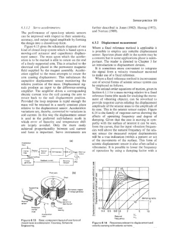
nals produce an input to the difference-sensing The second-order equations of motion, given in
amplifier. The amplifier drives a corresponding Section 6.1.1 for a mass moving relative to a fixed
electric current into the coil causing the arm to reference frame (the mode for studying the move-
rotate back to the null displacement position. ment of vibrating objects), can be reworked to
Provided the loop response is rapid enough the provide response curves relating the displacement
mass will be retained in a nearly constant place amplitude of the seismic mass to the amplitude of
relative to the displacement sensor. Acceleration its case. This is the seismic sensor output. Figure
variations are, thereby, converted to variations in 6.14 is the family of response curves showing the
coil current. In this way the displacement sensor effects of operating frequency and degrze of
is used in the preferred null-balance mode in damping. Given that the case is moving in sym-
which error of linearity and temperature shift pathy with the surface of interest it can be seen,
are largely avoided. Only the more easily from the curves, that for input vibration frequen-
achieved proportionality between coil current cies well above the natural frequency of the seis-
and force is important. Servo instruments are mic sensor the measured output displacements
will be a true indication (within a percent or so)
of the movements of the surface. This form of
Acceleration seismic displacement sensor is also often called a
input
vibrometer. It is possible to lower the frequency
of operation by using a damping factor with a
Feedback Current
2 .o
Pivot axis (b)
1 .o
0.5
Permanent magnet
of torque generator
g ratio
0.2
5
Pendulous 0.1
inertial \i bearing
mass 0.3 0.5 0.8 1.0 2 5 10
W
Acceleration I -
Input Natural
frequency W"
Figure 6.13 Basic component layout of one form of
closed-loop accelerometer. Courtesy, Schaevitz Figure 6.14 Responses relevant to displacement and
Engineering. velocity sensing with seismic sensors.