
Page 111 - Instrumentation Reference Book 3E
P. 111
96 Vibration
vibration sensing possible influence error sources
include temperature variation of the sensor, pos-
sible magnetic field fluctuations (especially at
radio frequency), and existing background acous-
tic noise vibrations. Each of these might induce
erroneous signal.
A good test for influence parameters is to fully
connect the system, observing the output when
the measurand of interest is known to be at zero
level. Where practical the important error inputs
can be systematically varied to see the sensor
response. Many a vibration measurement has
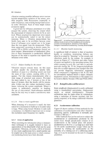
finally been seen to be worthless because some Figure 6.7 In machine health monitoring the normal
form of influence error turned out to be larger vibration levels of parts of the installation are recorded to
provide a normal signature. Variations of this indicate
than the true signal from the measurand. Vibra- changes in mechanical conditioning. Courtesy, Bruel & Kjaer.
tions apparently occurring at electric mains fre-
quency (50 or 60Hz) and harmonics thereof are 6.1.3.1 Machine health monitoring
most suspect. Measurement of mechanical vibra- A significant field of interest is that of machine
tion at these frequencies is particularly difficult health, or condition, monitoring; failures can
because of the need to separate true signal from often be avoided by “listening” to the sounds and
influence error noise. vibrations made by the system. An example is
shown in Figure 6.7. Vibration and other forms
of sensor are applied to the operating system, first
6.1.2.5 Subject loading by the sensor whilst running in early life, and then at periodic
intervals during life. If the frequencykimplitude
Vibration sensors contain mass. As this mass data (the so-called signature) has changed then this
is made smaller the sensitivity usually falls. can provide diagnostic information suggesting
Addition of mass to a vibrating system can load which component is beginning to fail. It can then
the mass of that system, causing shifts in fre- be conveniently replaced before a major, untimely
quency. For this reason manufacturers offer a breakdown occurs. Introduction to this aspect is to
wide range of attached type sensors. Provided be found in Bently Nevada (1982) and Wells (1981).
the mass added is, say, 5 percent or less of the
mass of interest, then the results will be reason-
able. Cables can also reduce mechanical comp- 6.2 Amplitude calibration
liance, reducing the system amplitude. Where a
system is particularly sensitive to loading, Static amplitude (displacement) is easily calibrated
the use of non-contact, fixed-reference methods using a standardized micrometer, displacement
may be the only way to make a satisfactory mea- sensor, or optical interferometry. Dynamic
surement. calibrations may be made either by comparison,
using a technique of known accuracy and fre-
quency response, or by using a calibrated vibration
generator.
6.1.2.6 Time to reach equilibrium
When damping of a structure is small, the time 6.2.1 Accelerometer calibration
taken for a resonance to build up to its peak value
is large. When using forced vibration to seek such Figure 6.8 shows outlines of three methods for the
a resonance, it is therefore important not to sweep calibration of accelerometers and other vibration-
the excitation input frequency too rapidly. measuring sensors. Calibration is normally per-
formed at 500 rad s-l.
Other methods that can be used are to subject the
accelerometer to accelerations produced by the
6.1.3 Areas of application earth’s force. Simple pseudo-static rotation of an
When searching for information about a measure- accelerometer in the vertical plane will produce
ment technique it is usually helpful to have an accelerations in the 0 to il g range (g is used here
appreciation of the allied fields which use the same for the earth’s acceleration). Larger values can be
equipment. Vibration, of course, will be of interest obtained by whirling the accelerometer on the
in very many applications but a small number can extremity of a rotating arm of a calibrating centri-
be singled out as the main areas to which commer- fuge, or it can be mounted on the end of a hanging
cial marketing forces have been directed. pendulum.