
Page 106 - Instrumentation Reference Book 3E
P. 106
References 91
1
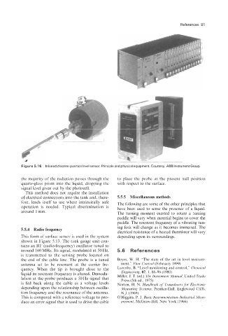
Figure 5.1 6 Infrared discrete-position level sensor. Principle and physical equipment. Courtesy, ABB Instrument Group.
the majority of the radiation passes through the to place the probe at the present null position
quartz-glass prism into the liquid, dropping the with respect to the surface.
signal level given out by the photocell.
This method does not require the installation
of electrical connections into the tank and, there- 5.5.5 Miscellaneous methods
fore, lends itself to use where intrinsically safe The following are some of the other principles that
operation is needed. Typical discrimination is have been used to sense the presence of a liquid.
around 1 mm. The turning moment exerted to rotate a turning
paddle will vary when material begins to cover the
paddle. The resonant frequency of a vibrating tun-
5.5.4 Radio frequency ing fork will change as it becomes immersed. The
electrical resistance of a heated thermistor will vary
This form of surface sensor is used in the system depending upon its surroundings.
shown in Figure 5.13. The tank gauge unit con-
tains an RF (radio-frequency) oscillator tuned to
around 160 MHz. Its signal, modulated at 50 Hz, 5.6 References
is transmitted to the sensing probe located on
the end of the cable line. The probe is a tuned Boyes, W. H. “The state of the art in level measure-
antenna set to be resonant at the carrier fre- ment,” Flow Control (February 1999)
quency. When the tip is brought close to the Lazenby, B. “Level monitoring and control,” Clzenzical
liquid its resonant frequency is altered. Demodu- Engineering, 87. 1, 88-96 (1980)
lation at the probe produces a 50 Hz signal that Miller, J. T. (ed.) The Instrument Manual, United Trade
Press (5th ed., 1975)
is fed back along the cable as a voltage levels Norton, H. N. Handbook of Transducers for Electronic
depending upon the relationship between oscilla- Measuring Systems, Prentice-Hall. Englewood Cliffs,
tion frequency and the resonance of the antenna. N.J. (1969)
This is compared with a reference voltage to pro- OHiggins, P. J. Basic Instrumentation-Industrial Meas-
duce an error signal that is used to drive the cable urement, McGraw-Hill, New York (1966)