
Page 103 - Instrumentation Reference Book 3E
P. 103
88 Measurement of level and volume
Plug-in electronics are easily Plastic cover provides additional
removed for maintenance protection for electronic circuits
Cable entry threaded for Screw on aluminum
20 mm conduit entry L / alloy cover
Large terinnlnals facilitate
connection of wires to controller
Weatherproof type cable gland ,,
as standard Silicon rubber O.ring
makes head waterproof
Threepoint fix ,ng of head to boss Terminals protected by molded
enabler head to be DC isitioned with I plastic spacer
cable entry In most convenient
position Robust sensor head made of
diecast aluminum alloy (cast iron
alternative available)
Blowout plug Releases internal l
Walkerite gasket acts
*u !( unlikely event of the failure of
as weatherproof seal pressure in excess of 2 bar in th e
the pressure seals
insulation bush
O-rings seal head to
pressures UP to 40 bar / 1 Clamping collar holds rod insulation
,/ against tapered bush
Mild steel or stainless steel boss,
threaded ltn BSP or lin NPT
BS. DIN or NP flanges are
available
E or polypropylene Insulates
protects electrode rod
for most sppllcatjons
Electrode rod of mlld steel
(fully covered electrode) or
stainless steel (part covered)
electrode), 12mm diameter
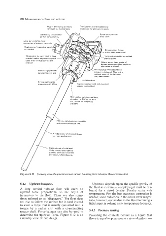
Figure 5.11 Cutaway view of capacitance level sensor. Courtesy, Kent Industrial Measurements Ltd.
5.4.4 Upthrust buoyancy Upthrust depends upon the specific gravity of
the fluid so instruments employing it must be cali-
A long vertical tubular float will exert an brated for a stated density. Density varies with
upward force proportional to the depth of temperature. For the best accuracy, correction is
immersion in the fluid. These are also some- needed; some reduction in the actual error magni-
times referred to as “displacers.” The float does tude, however, occurs due to the float becoming a
not rise to follow the surface but is used instead little larger in volume as its temperature increases.
to exert a force that is usually converted into a
torque by a radius arm with a counteracting 5.4S
torque shaft. Force-balance can also be used to
determine the upthrust force. Figure 5.12 is an Providing the contents behave as a liquid that
assembly view of one design. flows to equalize pressures at a given depth (sone