Page 101 - Instrumentation Reference Book 3E
P. 101

86  Measurement of  level and volume


                                                                                Externa,
                                                                                indicator column

                                                                                 Indicators turn
                                                                                toward  magnet
                                                                                 Float in srill tube
                                                                                 contalnr permanent
                                                                                 magnet at Itwid level


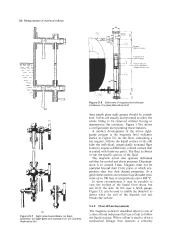
                                                      Figure 5.8  Schematic of magnetic level indicator
                                                      installation. Courtesy,Weka-Besta Ltd.

                                                      than simple glass sight gauges should be consid-
                                                      ered. Valves are usually incorporated to allow the
                                                      whole  fitting  to  be  removed  without  having  to
                                                      depressurize the  container.  Figure  5.7(b) shows
                                                      a configuration incorporating these features.
                                                        A  modern  development  of  the  above  sight-
                                                      gauge  concept  is  the  magnetic  level  indicator
                                                      shown in  Figure  5.8.  As  the  float, containing a
                                                      bar magnet, follows the liquid surface in the still
                                                      tube  the individual,  magnetically  actuated  flaps
                                                      rotate to expose a differently colored surface that
                                                      is coated with luminous paint. The float is chosen
                                                      to suit the specific gravity of the fluid.
                                                        The  magnetic  action  also  operates  individual
                                                      switches for control and alarm purposes. Discrimin-
                                                      ation  is  to  around  5mm.  Magnets must  not  be
                                                      operated beyond their Curie point, at which  tem-
                                                      perature  they  lose  their  desired  properties. As  a
                                                      guide these systems can measure liquids under pres-
                                                      sures up to 300 bars at temperatures up to 400 "C.
                                                        In  some circumstances  it  may  be  possible to
                                                      view  the  surface  of  the  liquid  from  about  but
                                                      not  from  the  side.  In  this  case  a  hook  gauge,
                                                      Figure 5.9, can be used to enable the observer to
                                                      detect  when  the  end  of  the  dipstick  rod  just
                                                      breaks the surface.

                                                      5.4.2  Float-driven instruments
                                                      The magnetic indicator described above is one of
                          ib)                         a class of level indicators that use a float to follow
             Figure 5.7  Sight-glasslevel indicator. (a) Basic   the liquid surface. Where a float is used to drive a
             schematic. (b) Sight-glass with automatic cut-off. Courtesy,
             Hopkinsons Ltd.                          mechanical  linkage  that  operates  a  remotely
   96   97   98   99   100   101   102   103   104   105   106