
Page 96 - Instrumentation Reference Book 3E
P. 96
easurement of level
volume
P. H. SVDENHAM and W. H. BOYES
5 .I I nt r o d u ct i o n with respect to a chosen datum, for automatic con-
trol purposes, or for manually read records.
Many industrial and scientific processes require Simple installations may be able to adopt inex-
knowledge of the quantity of content of tanks pensive manual methods such as a dipstick.
and other containers. In many instances it is not Automatic control applications, however, will
possible. or practical: to directly view the interior. require control signals for operation of a process
Parameters of interest are generally level of the actuator or alarm. For these cases there are avail-
contents, volume, or simply the presence of sub- able several options of output signal which
stances. Sensors may be needed, Figure 5.1, to include indirect electric contacts and electronic
detect high or low level states for alarm or control proportional outputs, and direct flow and pneu-
use; to provide proportional readout of the level matic valving.
Electronic
unit Controller
out-
I" 1-
High 1
I" 2- *
-
High 2
Digital readout
of lwei
-
Law 2
(Set points)
(e)
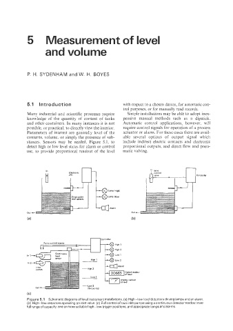
Figure 5.1 Schematic diagrams of level instrument installations. (a) High-low level detectors driving lamps and an alarm.
(b) High-low detectors operating on inlet valve. (c) Full control of two inlet pumps using a continuous detector readout over
full range of capacity, one or more settable high-low trigger positions, and appropriate lamps and alarms.