
Page 93 - Instrumentation Reference Book 3E
P. 93
78 Measurement of strain
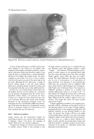
Figure 4.15 Brittle lacquer used on a specimen Courtesy, Photolastic Division, Measurements Group Inc
A layer of special lacquer is carefully and consist- through another grating that is comparable but
ently applied to the surface to be studied. The not identical, dark and brighter regions-called
lacquer is dried under controlled conditions, where- “fringes”-will alternate. The dark regions corres-
upon it becomes brittle and therefore cracks if and pond to where spaces in one grating block light
when the part is strained above a certain threshold. that has come through gaps in the other grating;
Moreover, the higher the surface strain, the closer bright regions arise when the gaps are super-
together are the cracks. It is best to coat a calibra- posed. The small difference between the gratings
tion bar in the same way and at the same time as the can be one of orientation, or of separation of
test part. Bending the bar then gives a range of their elements. For instance, if one grating has
known strains along it and the crack pattern 1000 lines per centimeter and its neighbor 1001
observed at different points on the live surface can lines, there will be a dark fringe every centimeter,
be compared with that seen on the calibration bar. with bright ones in between them. Now suppose a
In this way, the critical points where there are 1000-line grating is etched on a surface and
the highest stresses on the surface of a structure another placed just above it; a strain of in
can be quickly recognized and the strain levels the surface will change the former into a 1001-line
identified within about *25 percent (of those grating and mean that fringes (seen in this case in
levels) over a range of strains from 0.05 per cent light reflected off the surface) appear every cen-
to 0.2 percent. Because the cracks form perpen- timeter. The larger the strain, the more closely
dicularly to the maximum principal stress, the spaced the fringes.
technique has the considerable additional advant- Fringes appearing parallel to the original grat-
age of showing the directions of principal stresses ing lines will be a measure of the direct strain of
all over a structure. Figure 4.15 shows the sort of one grating relative to the other. Fringes appear-
crack pattern that can be observed. ing perpendicular to the original grating lines will
indicate rotation of one grating relative to the
other. In general the fringes will be at an angle
4.8.2 Patterns on surfaces
to the grating lines; therefore one pair of gratings
Large strains can be determined simply by will give a direct strain and a shear strain compon-
inscribing a pattern on a surface and noting how ent. Two pairs, Le., a grid or mesh, will give two
it changes. Figure 4.16 shows the changes of direct strains and the associated shear strain and
shape observed in one such investigation. will thus permit a complete surface strain deter-
Using moire fringes can increase the sensitivity mination to be made, i.e., principal strains and
to smaller strains. When a fine grating is seen principal strain directions.