
Page 95 - Instrumentation Reference Book 3E
P. 95
80 Measurement of strain
ponds to each fringe order. Since the stress nor-
mal to the unloaded boundaries of the model is
zero, Le., Q = 0, it is a relatively simple matter to
determine the stress all along the unloaded
boundaries. Determination of the stresses in the
interior of the model is also possible but requires
complex stress separation.
Normally a monochromatic light source is
used, but white light has the advantage that the
first-order fringe can be distinguished from
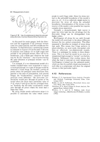
Figure 4.18 Use of a polariscopeto determine principal
stress directions. Courtesy Sharples Stress Engineers Ltd. higher orders.
Birefringence all along the ray path through
the model will contribute to the phase difference
As discussed for strain gauges, both the direc- between the two optical components. The effect
tion and the magnitude of the principal stresses measured is therefore an integral of stress along
come into stress analysis, and this complicates the that path. This means that fringe patterns in
situation. To find directions, a polariscope system photo-elasticity are most easily interpreted with
as indicated in Figure 4.18 can be used; if the axes thin-or effectively two-dimensional-models.
of polarizer and analyzer are at right angles and There is a technique for studies in three dimen-
parallel to the principal stresses, there will be no sions. This is to load the model in an oven at a
interference. just a black spot whatever the load temperature high enough to “anneal” out the bire-
may be. So the “isoc1inics”-loci of points having fringence. Subsequent slow cooling means that
the same direction of principal stresses--can be when the load is removed at room temperature
established. birefringence is locked into the unloaded model,
For example, if a two-dimensional model of a which can then be carefully sliced; examination of
loaded notched beam were examined in such a each slice in a polariscope will show the original
crossed polariscope two types of fringes would be stresses in that particular region.
observed: a black fringe, the isoclinic, joining all
points where the principal stress directions were
parallel to the axes of polarization, and colored 4.10 References
fringes, the “isochromatics,” contours of equal
principal stress difference. The first-order iso- Holister, G. S. Experimental Stress Analysis, Principles
chromatic would pass through all points of the and Methods. Cambridge University Press, Cam-
model where the stress had a particular value of bridge (1 967)
P-Q, where P and Q are the two principal stres- Kuske, A. and G. Robertson, Photoelastic Stress Ana-
lysis, Wiley, New York (1974)
ses. Similarly the nth-order isochromatic would Theocaris, P. S. Moire Fringes in Strain Analysis, Per-
pass through all points where the stress had n gamon Press, Oxford (1969)
times that value. Window, A. L. and G. S. Holister, (eds) Strain
By using simple tensile calibration strips it is Gauge Technology, Allied Science Publishers, London
possible to determine the value which corres- (1982)