
Page 98 - Instrumentation Reference Book 3E
P. 98
Calibration of level-measuring systems 83
Granular materials will not generally flow to also exists due to the actual depth to which the
form a flat surface as do liquids. The angle of float sinks to provide its necessary buoyancy
repose of the material and the form of input and force. This varies with material density which
output porting will give rise to error in volume often varies with temperature.
calculations if the actual geometry is not allowed A second class of errors arise due to tempera-
for in use of a single point sensor. ture and, to a lesser extent, pressure changes to
Turbulence occurring at the sensor, caused by the contents. Where the required measurement is
material flow in the container or by vibrations a determination of the volume or mass of the con-
acting on ithe container, may also be a source of tents, use is made of level as an indirect step toward
error. It is common practice to mount a mechan- that need. All materials change volume with chang-
ical level sensor in some form of integrating ing temperature. It may therefore be necessary to
chamber that smooths out transient dynamic vari- provide temperature measurements so that level
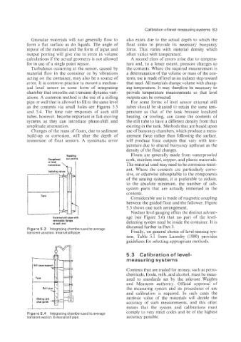
ations. A common method is the use of a stilling outputs can be corrected.
pipe or well that is allowed to fill to the same level For some forms of level sensor external still
as the contents via small holes-see Figures 5.3 tubes should be situated to retain the same tem-
and 5.4. The time rate responses of such still perature as that of the tank because localized
tubes. however. become important in fast-moving heating, or cooling, can cause the contents of
systems as they can introduce phase-shift and the still tube to have a different density from that
amplitude attenuation. existing in the tank. Methods that are based upon
Changes of the mass of floats, due to sediment use of buoyancy chambers, which produce a meas-
build-up or corrosion. will alter the depth of urement force rather than following the surface.
immersion of float sensors. A systematic error will produce force outputs that vary with tem-
perature due to altered buoyancy upthrust as the
density of the fluid changes.
Floats are generally made from waterproofed
Rodding
Gaugehead out paints cork, stainless steel, copper, and plastic materials.
The material used may need to be corrosion-resist-
ant. Where the contents are particularly corro-
sive, or otherwise inhospitable to the components
of the sensing systems, it is preferable to reduce.
to the absolute minimum. the number of sub-
system parts that are actually immersed in the
contents.
Considerable use is made of magnetic coupling
between the guided float and the follower. Figure
5.5 shows one such arrangement.
Nuclear level gauging offers the distinct advant-
External nil1 pipe with age (see Figure 5.6) that no part of the level-
removable flanges detecting system need be inside the container. It is
at each 0nd
discussed further in Part 3.
Figure 5.3 Integrating chamber used to average
transient variation. internal still pipe. Finally, on general choice of level-sensing sys-
tem, Table 5.1 from Lazenby (1980) provides
guidelines for selecting appropriate methods.
5.3 Calibration of level-
measuring systems
Contents that are traded for money, such as petro-
chemicals, foods, milk, and alcohol, must be meas-
ured to standards set by the relevant Weights
and Measures authority. Official approval of
the measuring system and its procedures of use
and calibration is required. In such cases the
intrinsic value of the materials wili decide the
accuracy of such measurements, and this often
means that the system and calibrations must
Figure 5.4 Integrating chamber used to average comply to very strict codes and be of the highest
transient motion. External still pipe. accuracy possible.