
Page 102 - Instrumentation Reference Book 3E
P. 102
Methods providing full-range level measurement 87
sophisticated form that uses a pre-wound
“Neg’ator” (also called “Tensator”) spring torque
Scale graduated in mm motor that has its torque characteristic tailored
to vary as more tape is to be supported during
windout.
The production costs of precision mechanical
systems can make them less attractive than elec-
tronic equivalents but such systems do have
the advantages that no electrical power supply
is needed. Previously, another advantage of
mechanical level systems was the fact that a wider
range of plant operators easily understood them.
This is no longer necessarily the case. It is com-
monly now recommended that non-contacting or
non-invasive level measurements be the measure-
ments of first choice where possible.
Figure 5.9 Hook-type level indicator
5.4.3 Capacitance probes
located readout device of the linkage motion,
there is need to ensure that the linkage geometry The electrical capacitance C between two adja-
does not alter the force loading imposed on the cent electrically conducting surfaces of area A,
float, for this will alter its immersion depth and separated by distance d, is given by
introduce error. Frictional forces exerted by the A
linkage can also introduce error. C=E-
Compensation for changes in linkage weight d
as a float moves is achieved by using such The constant of proportionality E is the dielectric
mechanisms as counterbalance masses and constant of the material between the plates. An
springs. Figure 5.10 shows the construction of a electrode is suspended in the container, electrically
insulated from it. Presence of liquid or granular
material around the electrode alters the capacitance
between the electrode and the walls. The capacit-
ance is sensed by electronic circuitry. Figure 5.11 is
a cut-away view of one form.
The electrode is tailored to the situation; forms
include rigid metal rods, flexible cables, and
shielded tubes. Capacitance sensors rely on uni-
form contact being maintained between the con-
tents and a long thin electrode. Where they are
used for level sensing of granular materials, such
as wheat, the material has a tendency to pile non-
uniformly around the electrode, producing what
is known as “rat-holing.’’ Placing the electrode at
an angle to the vertical helps reduce this as it
alters the angle of repose of the material, helping
it to follow the stem more consistently. As the
method provides continuous readout of level over
its full electrode length, circuitry can also be used
to provide multiple on-off setpoints for alarms
and control functions. The same principle is used
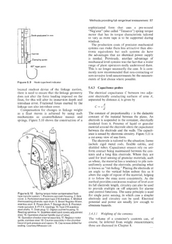
Figure 5.1 0 Spring torque motor compensated float- for single point sensing, in which case a simpler
type transfer system. 1. Precision cast main housing. 2. Side
cover. 3. Perforated steel tape type 316 stainless. 4. Molded electrode and circuitry can be used. Electrical
thermosetting phenolic tape drum. 5. Broad Neg’ator Motor, potential and power are usually low enough to
stainless steel. 6. Power drum. 7. Storage drum. 8. Precision eliminate hazards.
made sprocket. 9. P.T F. E. bearings. 10.Type 316 stainless
steel shafts. 11. Drain plug. 12. Digital counter housing. 13.
Reading window. 14. Stainless steel band covers adjustment 5.4.3.1 Weighing of the contents
slots. 15. Operation checker handle (out of view).
16. Operation checker internal assembly. 17. Neg’ator motor The volume of a container’s contents can, of
guide, stainless steel. 18. Counter assembly in the chamber
beyond tank pressure and vapors. 19. Cap screws drilled for course, be inferred from weight measurements;
sealing. CourtesyWhessoe Ltd. these are discussed in Chapter 8.