
Page 97 - Instrumentation Reference Book 3E
P. 97
82 Measurement of level and volume
As well as the obvious liquid substances, such Threaded rod nut
as water, oil, petroleum, and milk, level sensors and washer \
have been successfully applied to measurement of F F
solids such as flour, mineral ores, food grain, and
even potatoes and coal. Two-phase systems are
also often measured, for example liquid and froth
levels in beer making and for mineral slurries.
Due to the extensive need for this basic process
parameter many types of level instruments are
available; their installation details are important.
A useful tutorial introduction to level measure-
ment is available in Lazenby (1980) and Norton
(1969). O’Higgins (1966) and Miller (1975) also
make valuable contributions.
5.2 Practice of level
measurement
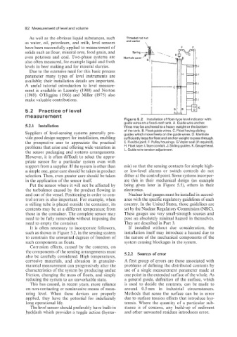
Figure 5.2 Installation of float-type level indicator with
guide wires on a fixed-roof tank. A. Guide wire anchor.
5.2.1 Installation Wires may be anchored to a heavy weight or the bottom
of the tank. B. Float guide wires. C. Float having sliding
Suppliers of level-sensing systems generally pro- guides which move freely on the guide wires. D. Manhole
vide good design support for installation, enabling sufficiently large for float and anchor weight to pass through.
the prospective user to appreciate the practical E. Flexible joint. F. Pulley housings. G.Vapor seal (if required).
problems that arise and offering wide variation in H. Float tape. I.Tape conduit. J. Sliding guides. K. Gauge head.
the sensor packaging and systems arrangements. L. Guide wire tension adjustment.
However, it is often difficult to select the appro-
priate sensor for a particular system even with
support from a supplier. If the system is other than esis) so that the sensing contacts for simple high-
a simple one, great care should be taken in product or low-level alarms or switch controls do not
selection. Then, even greater care should be taken dither at the control point. Some systems incorpor-
in the application of the sensor itself. ate this in their mechanical design (an example
Put the sensor where it will not be affected by being given later in Figure 5.5), others in their
the turbulence caused by the product flowing in electronics.
and out of the vessel. Positioning in order to con- Nuclear level gauges must be installed in accord-
trol errors is also important. For example, when ance with the specific regulatory guidelines of each
a stilling tube is placed outside the container, its country. In the United States, those guidelines are
contents may be at a different temperature from set by the Nuclear Regulatory Commission (NRC).
those in the container. The complete sensor may These gauges use very small-strength sources and
need to be fully removable without imposing the pose an absolutely minimal hazard in themselves.
need to empty the container. They are described in Part 3.
It is often necessary to incorporate followers, If installed without due consideration, the
such as shown in Figure 5.2, in the sensing system installation itself may introduce a hazard due to
to constrain the unwanted degrees of freedom of the nature of the mechanical components of the
such components as floats. system causing blockages in the system.
Corrosion effects, caused by the contents, on
the components of the sensing arrangements must 5.2.2 Sources of error
also be carefully considered. High temperatures,
corrosive materials, and abrasion in granular- A first group of errors are those associated with
material measurement can progressively alter the problems of defining the distributed contents by
characteristics of the system by producing undue use of a single measurement parameter made at
friction, changing the mass of floats, and simply one point in the extended surface of the whole. As
reducing the system to an unworkable state. a general guide, definition of the surface, which
This has caused, in recent years, more reliance is used to decide the contents, can be made to
on non-contacting or noninvasive means of meas- around 0.5 mm in industrial circumstances.
uring level. When these devices are properly Methods that sense the surface can be in error
applied, they have the potential for indefinitely due to surface tension effects that introduce hys-
long operational life. teresis. Where the quantity of a particular sub-
The level sensor should preferably have built-in stance is of concern, any build-up of sediment
backlash which provides a toggle action (hyster- and other unwanted residues introduces error.