
Page 110 - Instrumentation Reference Book 3E
P. 110
introduction 95
at -
Theoretical peak
2.0
Instantaneous
amplitude x 1 .o
(or, see sectioOn
6.3.4, gives ratio
relative displacement
0.5
relative acceleration
for accelerometers1
0.2
0.1
0.2
0.1 - 0.5 liO 2
- Natural
w
=n frequency
W"
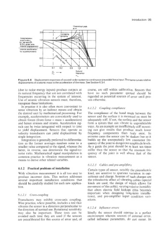
Figure 6.6 Displacement responses of second-order system to continuous sinusoidal force input.The same curves relative
displacements of a seismic mass to the acceleration of the mass. See Section 6.3.4.
(due to noise energy inputs) produce outputs at course, are still within calibration. Sensors that
its natural frequency that are not correlated with have no such parameter quoted should be
frequencies occurring in the system of interest. regarded as potential sources of error until pro-
Use of seismic vibration sensors must, therefore, ven otherwise.
recognize these limitations.
In practice it is also often more convenient to
sense vibration by an indirect means and obtain 6.1.2.2 Coupling compliance
the desired unit by mathematical processing. For The compliance of the bond made between the
example, accelerometers are conveniently used to sensor and the surface it is mounted on must be
obtain forces (from force = mass x acceleration) adequately stiff. If not, the surface and the sensor
and hence stresses and strains. Acceleration sig- form a system that can vibrate in unpredictable
nals can be twice integrated with respect to time ways. As an example an insufficiently stiff mount-
to yield displacement. Sensors that operate as ing can give results that produce much lower
velocity transducers can yield displacement by frequency components than truly exist. In
single integration. extreme cases the sensor can be shaken free as it
Integration is generally preferred to differentia- builds up the unexpectediy low resonance fre-
tion as the former averages random noise to a quency of the joint to dangerous amplitude levels.
smaller value compared to the signal, whereas the As a guide the joint should be at least ten limes
latter, in reverse, can deteriorate the signal-to- stiffer than the sensor so that the resonant fre-
noise ratio. Mathematical signal manipulation is quency of the joint is well above that of the
coimon practice in vibration measurement as a sensor.
means to derive other related variables.
6.1.2.3 Cables and pre-amplifiers
6.1.2 Practical problems of installation Certain types of sensor, notably the piezoelectric
With vibration measurement it is all too easy to kind, are sensitive to spurious variation in cap-
produce incorrect data. This section addresses acitance and charge. Sources of such charges are
several important installation conditions that the triboelectric effect of vibrating cables (special
should be carefully studied for each new applica- kinds are used, the design of which allows for
tion. movement of the cable), vairying relative humidity
that alters electric field leakage (this becomes
important when designing long-term installa-
6.1.2.1 Cross-coupling tions), and pre-amplifier input condition vari-
Transducers may exhibit cross-axis coupling. ations.
Wise practice, where possible, includes a test that
vibrates the sensor in a direction perpendicular to 6.1.2.4 Inyuence errors
the direction of normal use. Rotational sensitivity
may also be important. These tests can be Ideally the sensor should operate in a perfect
avoided each time they are used if the sensors environment wherein sources of external error,
are precalibrated for this source of error and, of called influence parameters, do not occur. In