
Page 113 - Instrumentation Reference Book 3E
P. 113
98 Vibration
I I
k
--y
Plate Of ,“,erest Mountlng arrangement
That IS vibrating lone Rind!
Figure 6.9 Schematic layout of open-loop, seismic- g*qg
form, vibration sensor. Seismic mass
Linear variable differential ___
tranriormer LVDT senses
*--+
Figure 6 11 Displacement sensing of mass motion in
senr,tive accelerometers can be achieved by many methods This unit
dirwtian
Accelerometer ~ uses unbonded strain gauges. Courtesy, Statham
instruments Inc
attached to
subject Of
C
Figure 6.10 Diagrammatic view of a spring-mass
seismic sensor that uses parallel flexure-strip spring
suspension and inductive sensor of mass displacement.
Courtesy, Schaevitz Engineering.
Important design parameters of a spring are
the compliance, amplitude range, fatigue life,
constancy of rate with time, temperature, and
other influence effects and the suitability to be
packaged to produce a suitable sensor unit. Center mounted Inverted center
compression
mounted compression
Except for the highest natural frequency sensors ICMI IiCM)
the masses used can be regarded as completely
rigid compared with the spring element.
Rotary forms of the linear arrangement, shown
in Figure 6.9, are also available.
Sensing methods that have been used include
electrical-resistance sliding potentiometer, variable
inductance (see, for instance, Figure 6. lo), variable
reluctance, variable capacitance, electrical metallic
strain gauges (bonded and unbonded as in Figure
6.11) and semiconductor strain gauges, piezoelectric
crystal and magnetostrictive elements, position-
sensitive optical detectors, and electromagnet0 Annular shear
principles (that provide direct velocity sensing). (AS1 Deita shear
Sensors are often encapsulated. The encapsula- (OS1
tion takes many forms ranging from miniature 13 components)
units of total weight around 1 g through to 0.5 kg S = Spr~ng M = Mass B = Base C = Cable
units where the sensing mass must be physically P = Piezoelectric element R = Ciamping ring
F = Fastening surface
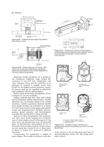
large. As simultaneous measurements in two or Figure 6.12 Examples of single- and three-axis
three directions are often required, seismic sensors accelerometers based on the piezoelectric sensor. Courtesy,
are also made that consist of two or three units, Bruel & Kjaer.
as shown in Figure 6.12, mounted in different
directions. tronic circuitry or by incorporating some form of
Compensation for temperature is needed in thermomechanical device into the spring-mass-
many designs. This is either performed in the elec- sensor layout.