
Page 322 - Instrumentation Reference Book 3E
P. 322
306 Chemical analysis: introduction
Eluant
reservoirs and
degassing
Eluant corn posi ti on
control
(gradient device)
Liquid flow pulse
damping device
system
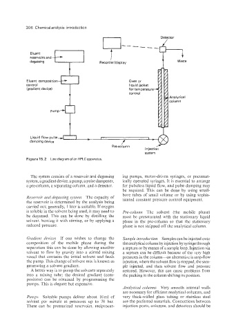
Figure 15.2 Line diagram of an HPLC apparatus.
The system consists of a reservoir and degassing ing pumps, motor-driven syringes, or pneumat-
system, a gradient device. a pump, a pulse dampener, ically operated syringes. It is essential to arrange
a pre-column, a separating column, and a detector. for pulseless liquid flow, and pulse damping may
be required. This can be done by using small-
bore tubes of small volume or by using sophis-
Reservoir and degassing system The capacity of ticated constant pressure control equipment.
the reservoir is determined by the analysis being
carried out; generally, 1 liter is suitable. If oxygen
is soluble in the solvent being used, it may need to Pse-cohrnzn The solvent (the mobile phase)
be degassed. This can be done by distilling the must be presaturated with the stationary liquid
solvent. heating it with stirring, or by applying a phase in the pre-column so that the stationary
reduced pressure. phase is not stripped off the analytical column.
Gradient devices If one wishes to change the Sample infrodiictioiz Samples can be injected onto
composition of the mobile phase during the the analytical column by injection by syringe through
separation this can be done by allowing another a septum or by means of a sample loop. Injection via
solvent to flow by gravity into a stirred mixing a septum can be difficult because of the very high
vessel that contains the initial solvent and feeds pressures in the column-an alternative is stop-flow
the pump. This change of solvent mix is known as injection, where the solvent flow is stopped, the sam-
generating a solvent gradient. ple injected, and then solvent flow and pressure
A better way is to pump the solvents separately restored. However, this can cause problems from
into a mixing tube; the desired gradient (com- the packing in the column shifting its position.
position) can be obtained by programming the
pumps. This is elegant but expensive.
Aiialytical coluims Very smooth internal walls
are necessary for efficient analytical columns, and
P~iriips Suitable pumps deliver about lOml of very thick-walled glass tubing or stainless steel
solvent per minute at pressures up to 70 bar. are the preferred materials. Connections between
These can be pressurized reservoirs, reciprocat- injection ports, columns, and detectors should be