
Page 325 - Instrumentation Reference Book 3E
P. 325
Polarography and anodic stripping voltammetry 309
15.3.1.3 Single-sweep cathode rq polarography
Another modification to d.c. polarography is
sweep cathode ray polarography. Here an
increasing d.c. potential is applied across the cell
but only once in the life of every mercury drop.
Drop times of about 7 seconds are used; the drop
is allowed to grow undisturbed for 5 seconds at a
preselected fixed potential, and a voltage sweep of
0.3 volt per second is applied to the drop during
the last 2 seconds of its life. The sharp decrease in
current when the drop falls is noted by the instru-
ment, and the sweep circuits are then automatic-
ally triggered back to zero. After the next 5 1 2 3 4
seconds drop growing time another voltage sweep -0.05V -0.55V
is initiated, is terminated by the drop fall, and so (a )
on. The use of a long persistence cathode ray tube 10 ppm Sb + 20 ppm Cu
enables the rapid current changes to be followed in M HCI. 80 mV apart. (4
easily with the trace remaining visible until the Sens 3 IIA FSD
next sweep. Permanent records can be made by
photography.
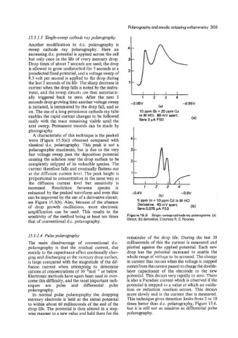
A characteristic of this technique is the peaked
wave (Figure 15.5(a)) obtained compared with
classical d.c. polarography. This peak is not a
polarographic maximum, but is due to the very
fast voltage sweep past the deposition potential
causing the solution near the drop surface to be
completely stripped of its reducible species. The
current therefore falls and eventually flattens out
at the diffusion current level. The peak height is
proportional to concentration in the same way as
the diffusion current level but sensitivity is
increased. Resolution between species is 1 2 3 4
enhanced by the peaked waveform and even this -0.4V -0.9v
can be improved by the use of a derivative circuit; (b)
see Figure 15.5(b). Also, because of the absence 5 ppm In + 10 pprn Cd in M HCI
of drop growth oscillations. more electronic Derivative. 40 mV apart. (b)
Sens 0.075 PA FSD
amplification can be used. This results in the
sensitivity of the method being at least ten times Figure 15.5 Single-sweep cathode ray polarograms. (a)
that of conventional d.c. polarography. Direct; (b) derivative. Courtesy R. C. Rooney.
15.3.1.4 Pulse polarography remainder of the drop life. During the last 20
The main disadvantage of conventional d.c. milliseconds of this the current is measured and
polarography is that the residual current, due plotted against the applied potential. Each new
mainly to the capacitance effect continually char- drop has the potential increased to enable the
ging and discharging at the mercury drop surface, whole range of voltage to be scanned. The change
IS large compared with the magnitude of the dif- in current that occurs when the voltage is stepped
fusion current when attempting to determine comes from the current passed to charge the double-
cations at concentrations of 10-5mol-' or below. layer capacitance of the electrode to the new
Electronic methods have again been used to over- potential. This decays very rapidly to zero. There
come this difficulty, and the most important tech- is also a Faradaic current which is observed if the
niques are pulse and differential pulse potential is stepped to a value at which an oxida-
polarography. tion or reduction reaction occurs. This decays
In normal pulse polarography the dropping more slowly and is the current that is measured.
mercury electrode is held at the initial potential This technique gives detection limits from 2 to 10
to within about 60 milliseconds of the end of the times better than d.c. polarography, Figure 15.6.
drop life. The potential is then altered in a step- but it is still not as sensitive as differential pulse
wise manner to a new value and held there for the polarography.