
Page 328 - Instrumentation Reference Book 3E
P. 328
312 Chemical analysis: introduction
-
explosives can also be analyzed by polarographic Plating step
techniques. Controlled potential
electr.
15.3.2 Anodic stripping voltammetry
Anodic stripping voltammetry is really a reversed fiaLL
polarographic method. Metals that are able to
form amalgams with mercury, e.g., Pb, Cu, Cd,
and Zn, can be cathodically plated onto a
mercury drop using essentially the same instru- Time
mentation as for polarography and then the Stripping step
amalgamated metal is stripped off again by chang- Anode stripping
ing the potential on the mercury drop linearly voltammetry
with time in an anodic direction. By recording (ASW
the current as a function of potential, peaks are - +
observed corresponding to the specific species M'
M'
present in the test solution; the heights of the M'
M'
peaks are proportional to concentration. M'
In practice, it is not very convenient to use a
mercury drop as cathode, and several other Time
types of electrode have been used, including a
rotating ring-disc electrode. The most often Figure 15.13 Plating and stripping steps. Courtesy
used, especially for water and environmental International Laboratory.
analysis, is a wax-treated mercury-coated gra-
phite rod. This, together with a silver/silver
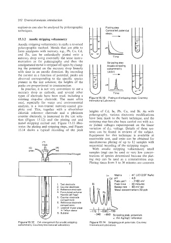
chloride reference electrode and a platinum heights of Cd, In, Pb, Cu, and Bi. As with
counter electrode, is immersed in the test solu- polarography, various electronic modifications
tion (Figure 15.12) and the plating out and have been made to the basic technique, and the
metal stripping carried out. Figure 15.13 illus- stripping step has also been carried out with a.c.
trates the plating and stripping steps, and Figure or pulsed voltages superimposed on the linear
15.14 shows a typical recording of the peak variation of d.c. voltage. Details of these sys-
tems can be found in reviews of the subject.
Equipment for this technique is available at
reasonable cost, and units can be obtained for
(7-1 simultaneous plating of up to 12 samples with
black sequential recording of the stripping stages.
With anodic stripping voltammetry small
samples (mg) can be used or very low concen-
trations of species determined because the plat-
ing step can be used as a concentration step.
Plating times from 5 to 30 minutes are common
41
In Matrix : 4F LiCl 0.5F NaAc
: 4.5
Plate pot7 : -1 100 mV
1. Test electrode Plate time : 30 minutes
2. Counter electrode Sweep rate : 60 mV sec
3. Reference electrode Metal concentrations 20 ppb
4. Formulated polymer
k flexible cell head
Compartment
161 I 6. Reference electrode
compartment
- I 7. Leached Vycor plugs -1 75 I -530 1-720
I
I
I IIA
in Teflon sleeve
-340 -650 Stripping peak potentials
v. the Ag/AgCI reference
Figure 15.12 Cell arrangement for anodic stripping Figure 15.14 Stripping peak potentials. Courtesy
voltammetry. Courtesy International Laboratory. International Laboratory.