
Page 513 - Instrumentation Reference Book 3E
P. 513
496 Optical measurements
detectors do not have this property, and this fact work function within a vacuum tube and causes
may determine the design of an instrument; for the release of electrons. These electrons are
example, many infrared spectrophotometers have attracted to a second electrode at a strongly posi-
elaborate optical arrangements for matching the tive voltage where each causes the emission of
intensity in order that a non-linear detector can several secondary electrons, which are attracted
be used. to a third electrode, and so on. By repeating this
It should be noted that in almost all detectors process at a series of “dynodes” the original elec-
the sensitivity varies markedly from point to tron stream is greatly multiplied. and results in a
point on the operative surface. Consequently if current of up to 100pA or so at the final anode.
the light beam moves with respect to the detector The spectral sensitivity is determined by the
the response will be altered. This effect is of crit- nature of the photocathode layer. The actual
ical importance in spectrophotometers and like materials need not concern us here; different
instruments; if a solution cell whose faces are types of cathodes are referred to by a series of
not perfectly flat and parallel is put into the beam numbers from S1 upwards. The response is linear,
it will act as a prism, move the beam on the response time rapid, and the sensitivity is large.
detector, and produce an erroneous result. Pre- The sensitivity may be widely varied by varying
cautions should be taken against this effect by the voltage applied to the dynode chain. Thus
ensuring that imperfect cells are not used.
Some detectors are sensitive to the direction of
polarization of incident light. Whilst in most optic- where S = sensitivity, V = voltage applied, and
al instruments the light is randomly polarized, the n = number of dynode stages. Conversely, where
distribution of intensities between the polariza- accurate measurements are needed, the dynode
tion directions is by no means uniform, especially chain voltage must be held extremely stable, since
after passage through monochromators. This between eight and fourteen stages are used. A
effect often causes no trouble, but it can be an variety of cathode shapes and multiplier config-
extremely abstruse source of error. urations are available. There is no point in having
a cathode of a much larger area than that actually
to be used as this will add unnecessarily to the
21.3.1 Photomultipliers
noise.
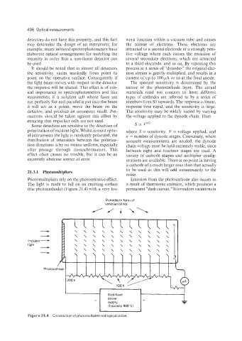
Photomultipliers rely on the photoemissive effect. Emission from the photocathode also occurs as
The light is made to fall on an emitting surface a result of thermionic emission, which produces a
(the photocathode) (Figure 21.4) with a very low permanent “dark current.” It is random variations in
Dynodes in form of
venetian blinds
\\\\\\\\\\\
lncident- \\\\\\\\\\\
light \\\\\\\\
Figure 21.4 Construction of photomultiplier and typical circuit.