
Page 514 - Instrumentation Reference Book 3E
P. 514
Detectors 497
this dark current-noise-which limit the ultimate Light
sensitivity. / / /
Photomultipliers are also discussed in Chapter
22, and excellent information on their use is given
in the makers’ catalogues to which the reader is
referred. It should be noted that they need very
stable high-voltage power supplies. are fragile,
and are easily damaged by overloads. When used
in instruments it is essential that interlocks are
provided to remove the dynode voltage before
any part ‘of the case is opened. Moreover, photo-
multipliers must never be exposed to sunlight,
even when disconnected.
Steei base
Figure 21.5 Simple photovoltaicdetector.
21.3.2 photovoltaic and photoconductive
detectors (photodiodes) cells” or “barrier-layer’’ cells. The simplest type
When light falls on a semiconductor junction there (see Figure 21.5) consists of a steel plate upon
is nearly always some effect upon the electrical which a layer of selenium is deposited. A thin
behavior of that junction, and such effects can be transparent film of gold is deposited on top of
made use of in light detectors. There are two main that to serve as an electrode. In earlier models an
categories, (I) those in which the action of the light annular contact electrode was sputtered on to
is used to generate an emf and (2) those in which facilitate contact with the gold film. Nowadays
the action of light is used to effectively alter the a totally encapsulated construction is used for
resistance of the device. Type (1) are referred to as cells of up to 30mm diameter.
“photovoltaic detectors”-sometimes called “solar The semiconductor action takes place at the
cells”-and type (2) are called “photoconductive steel-selenium junction; under the action of light
detectors.” There are some materials which show there is a build-up of electrons in the selenium,
photoconductive effects but which are not strictly and if an external circuit is made via the gold
semiconductors (for example. lead sulfide), but electrode a current will flow. If there is zero resist-
devices using these are included in the category ance in that external circuit then the current will
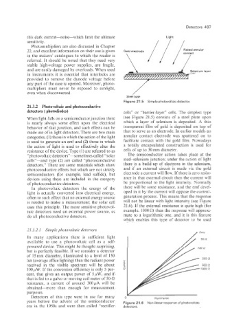
of photoconductive detectors. be proportional to the light intensity. Normaily
In photovoltaic detectors the energy of the there will be some resistance. and the emf devel-
light is actually converted into electrical energy, oped in it by the current will oppose the current-
often to such effect that no external energy source generation process. This means that the response
is needed to make a measurement; the solar cell will not be linear with light intensity (see Figure
uses this principle. The more sensitive photovol- 21.6). If the external resistance is quite high (for
taic detectors need an external power source. as example, 1000 0) then the response will approxi-
do all photoconductive detectors. mate to a logarithmic one, and it is this feature
which enables this type of detector to be used
21.3.2.1 Simple photovoltaic detectors
In many applications there is sufficient light
available to use a photovoltaic cell as a self-
powered device. This might be thought surprising,
but is perfectly feasible. If we consider a detector
of 15mm diameter, illuminated to a level of 150
lux (average office lighting) then the radiant power
received in the visible spectrum will be about
100 pW. If the conversion efficiency is only 5 per-
cent, that gives an output power of 5 ,uW> and if
that is fed to a galvo or moving coil meter of 50-0
resistance, a current of around 300,uA will be
obtained--more than enough for measurement
purposes.
Detectors of this type were in use for many 0 Illuminance
years befcre the advent of the semiconductor Figure 21.6 Non-linear response of photovoltaic
era in the 1950s and were then called “rectifier detectors.