
Page 519 - Instrumentation Reference Book 3E
P. 519
502 Optical measurements
+4*+*++
I
Source \I
driving
system
1
4
11 *
Variable
delay - Gate
Synchronizing unit Gating signal
signal
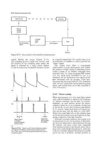
supply feeding the source (Figure 21.1 I). in a separate experiment. If a steady source is to
The sampling period is made very narrow, and be measured, an oscillator is used to provide the
the position of the sampling point within the “phase” signal.
phase is adjusted by a delay circuit (Figure This system both offers a considerable
21.12). It is necessary to establish the dark current improvement in noise performance and enables
the variation of light output of pulsating sources
within a phase to be studied. Although more
expensive than the beam chopping-PSD system
it is very much more convenient to use, as it
eliminates all the mechanical and optical prob-
lems associated with the chopper. These tech-
niques are also discussed in Part 4. (The American
term “boxcar” arises from the fact that the gating
signal, seen upside down on a CRT, resembles a
train of boxcars.)
(at I
1
1
21.4.5 Photon counting
A h When measurement of a very weak light indeed
with a photomultiplier is required the technique
of “photon counting” may be used. In a photo-
multiplier, as each electron leaves the photo-
cathode it gives rise to an avalanche of electrons
at the anode, of very short duration (see Section
21.3.1 above). These brief bursts of output cur-
( I b ’ A l I1 l rent can be seen with the help of a fast CRT.
-1 + bursts can be counted over a given period of time,
I i When very weak light falls on the cathode these
Although extremely sensitive, this system is by
I ’ Gate width giving a measure of the light intensity.
Deiay chosen
to sample kept as small no means easy to use. It is necessary to discrimin-
source at desired as possible ate between pulses due to photoelectrons leaving
point in cycle
the cathode and those which have originated
(C) from spurious events in the dynode chain; this is
Figure 21.12 Signals used in boxcar detector system. done with a pulse-height discriminator, which has
(a) Signal from detector produced by pulsating source
(as., CRT); (b) synchronizing signal derived from source; to be very carefully adjusted. Simultaneous double
(c) gating signal. pulses are also a problem. Another problem in