
Page 523 - Instrumentation Reference Book 3E
P. 523
506 Optical measurements
Table 21.1 Relation between transmission and absorbance The beam is divided into two by an array of
divided mirror elements at L and images of the
Tmisinissioii (%) Absorbance slit K are formed at R and S, the position of the
--___ reference and sample cells. A chopper disc driven
100 0
50 0.301 by a synchronous motor M allows light to pass
10 1 .0 through only one beam at a time. Both beams are
5 1.301 directed to T, a silica diffuser, so that the photo-
I 2.0 multiplier tube is presented alternately with sani-
0.1 3.0 ple and reference beams: the diffuser is necessary
__-
to overcome non-uniformities in the photoniulti-
I_____~i---____-I_----
plier cathode (see Section 21.4).
Table 21.2 Relation between wavelength and The signal from U is switched appropriately to
wavenumber satnple or reference circuits by the signal driving the
chopper M and the magnitudes compared. Their
W‘arei r umber
(no. of wuvesicnz) ratio gives the transmission which may be recorded
directly. or an absorbance figure may be calculated
~~
200 nim 50 000 from it and recorded. A microprocessor is used to
400 nm 25 000 control the functions of wavelength scanning, slit
500 nni 20 000 width, filter and lamp selection, and to effect any
1P 10 000 desired calculations on the basic transmission results.
5 I-& 3 000
10 P 1000
50 P 200 21.6.2 Spectroradiometers
The technique of measuring the spectral power dis-
(3) Tra~ismission/absorbaiice, infra- tribution (SPD) of a light source is termed “spectro-
red (2.5-25 pm). radiometry.” We may be concerned with the SPD in
relative or absolute terms. By “relative” we refer to
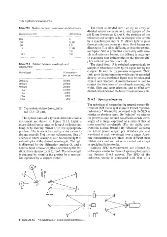
The optical parts of a typical ultraviolet-visible the power output per unit waveband at each wave-
instrument are shown in Figure 21.15. Light is length of a range, expressed as a ratio of that at
taken either from a tungsten lamp A or deuterium some specified wavelength. (For the visible spec-
lamp €3 by moving mirror C to the appropriate tmii this is often 560 mn.) By “absolute” we mean
position. The beam is focused by a mirror on to the actual power output per steradian per unit
the entrance slit E of the monochromator. One of waveband at each wavelength over a range. Abso-
a series of filters is inserted at F to exclude light of lute measurements are much more difficult than
submultiples of the desired wavelength. The light relative ones and are not often carried out except
is dispersed by the diffraction grating C, and a in specialized laboratories.
narrow band of wavelengths is selected by the exit Relative SPD measurements are effected by
slit K from the spectrum formed. The wavelength techniques similar to those of spectrophotometry
is changed by rotating the grating by a mechan- (see Section 21.6.1 above). The SPD of the
ism operated by a stepper motor. unknown source is compared with that of a
G
Figure 21.1 5 Typical ultraviolet-visible spectrophotometer.