
Page 518 - Instrumentation Reference Book 3E
P. 518
Detector techniques 501
air condensing or freezing on adjacent surfaces.
Peltier-effect cooling usually prevents these prob-
lems but does not achieve such low temperatures.
Unless special circumstances demand it, detector
cooling is less attractive than other methods of
noise reduction.
21.4.3 Beam chopping and phase-sensitive
detection
Random noise may be thought of as a mixture of
a large number of signals, all of different frequen-
cies. If a beam chopper is used, running at a fixed
frequency and the detector circuitry is made to
respond preferentially to that frequency, a con-
siderable reduction in noise can be achieved.
Although this can be effected by the use of tuned (C)
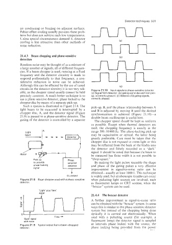
circuits in the detector circuitry it is not very reli- Figure 21 .I 0 Input signals to phase-sensitive detector.
able, as the chopper speed usually cannot be held (a) Signal from detector; (b) gating signal derived from pick-
precisely constant. A much better technique is to up, incorrectly phased; (c) detector and gating signals,
use a phase sensitive detector, phase locked to the correctly phased.
chopper disc by means of a separate pick-up.
Such a system is illustrated in Figure 21.8. The pick-up, B, and the phase relationship between A
Light beam to be measured is interrupted by a and B is adjusted by moving B until the desired
chopper disc, A, and the detector signal (Figure synchronization is achieved (Figure 21.10)-a
21.9) is passed to a phase-sensitive detector. The double-beam oscilloscope is useful here.
gating of the detector is controlled by a separate The chopper speed should be kept as uniform
as possible. Except when thermal detectors are
used, the chopping frequency is usually in the
range 300-10 000 Hz. The phase-locking pick-up
may be capacitative or optical, the latter being
greatly preferable. Care must be taken that the
chopper disc is not exposed to room light or this
may be reflected from the back of the blades into
the detector and falsely recorded as a “dark”
signal. It should be noted that because the beam to
be measured has finite width it is not possible to
“chop square.”
By making the light pulses resemble the shape
and phase of the gating pulses a very effective
improvement in signal-to-noise ratio can be
obtained-usually at least 1000: 1. This technique
d.c. output is widely used, but stroboscopic trouble can occur
Figure 21.8 Beam chopper used with a phase-sensitlve when pulsating light sources are involved, such
detector. as fluorescent lamps or CRT screens, when the
“boxcar” system can be used.
“Light” plus “dark
signal
21.4.4 The boxcar detector
A further improvement in signal-to-noise ratio
can be obtained with the “boxcar” system. In some
ways this is similar to the phase-sensitive detector
system but instead of the chopping being done
optically it is carried out electronically. When
o* Time- used with a pulsating source (for example, a
“Dark signal
with noise fluorescent lamp) the detector signal is sampled
Figure 21.9 Typical output from a beam-chopped at intervals phase locked with the source, the
detector. phase locking being provided from the power