
Page 517 - Instrumentation Reference Book 3E
P. 517
500 Optical measurements
improvements in performance may be expected.
All may be made sensitive to visible or near infra-
red radiation. The usual noise considerations
apply, and charge leakage between elements
implies that the scan interval must be less than
1 s. CIDs offer the possibility of very rapid read-
out, so that they may be introduced for television
purposes; they also permit sampling patterns
other than straightforward roster scanning. There
is also the possibility that, by using two variants
of CCDs in a single device, a CCD may develop
with dual red and blue sensitivities. CCDs are
also commonly used in video cameras at the pres-
ent time. The development of these devices con-
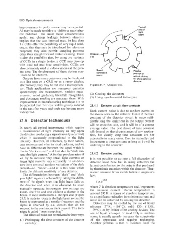
tinues to be intensive. motor optical pick-up
Outputs from array detectors may be displayed for phase-sensitive
as a line scan on a CRO or as a raster display; detector
alternatively, they may be fed into a microproces- Figure 21.7 Chopperdisc.
sor. Their applications are numerous; emission
spectroscopy, size measurement, position meas-
urement, robot guidance, facsimile recognition, (2) Cooling the detector;
and document reading are amongst them. With (3) Using synchronized techniques.
improvement in manufacturing technique it is to
be expected that their cost will be greatly reduced 21.4.1 Detector circuit time constants
in the next few years and their use become more
widespread. Dark current noise is due to random events on
the atomic scale in the detector. Hence if the time
constant of the detector circuit is made suffi-
21.4 Detector techniques ciently long the variations in the output current
will be smoothed out, and it will be of a correct
In nearly all optical instruments which require average value. The best choice of time constant
a measurement of light intensity we rely upon will depend on the circumstances of any applica-
the detector producing a signal (usually a current) tion, but clearly long time constants are not
which is accurately proportional to the light acceptable in many cases. Even in manually read
intensity. However, all detectors, by their nature, instruments a time constant as long as 1 s will be
pass some current when in total darkness, and we irritating to the observer.
have to differentiate between the signal which is
due to “dark current” and that due to “dark cur-
rent plus light current.” A further problem arises if 21.4.2 Detector cooling
we try to measure very small light currents or It is not possible to go into a full discussion of
larger light currents very accurately. In all detec- detector noise here but in many detectors the
tors there are small random variations of the dark largest contribution to the noise is that produced
current-i.e.. ”noise”-and it is this noise which by thermionic emission within the detector. Ther-
limits the ultimate sensitivity of any detector. mionic emission from metals follows Langmuir’s
The differentiation between “dark” and “dark law:
plus light” signals is achieved by taking the differ-
ence of the signals when the light beam falls on
the detector and when it is obscured. In some where Tis absolute temperature and i represents
manually operated instruments two settings are
made, one with and one without a shutter in the the emission current. Room temperature is
around 295 K in terms of absolute temperature,
beam. In most instruments a chopper disc (Figure so a significant reduction in emission current and
31.7) is made to rotate in the light beam so that the noise can be achieved by cooling the detector.
beam is interrupted at a regular frequency and the Detectors may be cooled by the use of liquid
signal is observed by as. circuits that do not nitrogen (77K, -196”C), solid C02 (195K,
respond to the continuous dark current. This tech- -79°C). or by Peltier effect cooling devices. The
nique is called “beam chopping.” use of liquid nitrogen or solid C02 is cumber-
The effects of noise can be reduced in three ways:
some; it usually greatly increases the complexity
(1) Prolonging the time constant of the detector of the apparatus and requires recharging.
circuitry; Another problem is that of moisture from the