
Page 520 - Instrumentation Reference Book 3E
P. 520
Intensity measurement 503
practice is the matching of “photon counting” with
“electrometer” (ie., normal) operation. It also has
to be remembered that it is a counting and not a
measuring operation, and since random statistics
apply, if it is required to obtain an accuracy of kl
percent on a single run then at least 10,000 counts D
must be made.
This technique is regularly used successfully in
what might be termed “research laboratory instru-
mentation”--Raman spectrographs and the like-
but is diMicult to set up and its use can really only
be recommended for those GTS~S where the require-
ment for extreme sensitivity demands it.
Intensity measurement
The term “light-intensity measurement” can be
wed to refer to a large range of different styles
of measurement. These can be categorized loosely
into (1) those where the spectral sensitivity of the
detector is used unmodified and (2) those where
the spectral sensitivity of the detector is modified
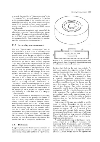
Figure 21.13 Cosineresponsephotometerhead.A:opal
deliberately to match some defined response glass cylinder; B: filter; C: detector; D: light shield developed
curve. Very often we are concerned with the com- to produce cosine response; E: metal case.
parison of light intensities where neither the spec-
tral power distribution of the light falling on the Incident light falls on the opal glass cylinder A,
detector nor its geometrical distribution with and some reaches the detector surface C after
respect to the detector will change. Such com- passing through the filter layer B. The detector
parative measurements are clearly in category may be of either the photoconductive or photo-
(I), aiid any appropriate detector can be used. voltaic type. The filter B is arranged to have
However. if, for example, we are concerned with a spectral transmission characteristic such
the purposes of lighting engineering where we that the detector-filter combination has a spectral
have to accurately measure “illuminance” or sensitivity matching that of the human eye. In
“luminance” with sources of any spectral or spatial many instruments the filter layer is an integral
distribution then we must use a photometer with part of the detector. The cosine response is
a spectra! response accurately matched to that of achieved by careful design of the opal glass A in
the human eye and a geometrical response accur- conjunction with the cylindrical protuberance D
ately following a cosine law; that is, a category in its mounting. The reading is displayed on an
(2) measurement. appropriately calibrated meter connected to the
Some “measurements” in category (1) are only head by a meter or two of a thin cable, so that the
required iio determine the presence or absence of operator does not “get in his own light” when
light, as in a very large number of industrial photo- making a reading.
electric controls and counters, burglar alarms, Instruments of this kind are available at a wide
street-lighting controls, and so on. The only critical range of prices, depending on the accuracy
points here are that the detector should be arranged demanded; the best instruments of this type can
that it receives only light from the intended source achieve an accuracy of 1 or 2 percent of the
and that it shall have sufficieiit response speed. illuminance with normal light sources. Better
Photodiodes and phototransistors are often used accuracy can be achieved with the use of a Dresler
aiid are robust, reliable, and cheap. Cadmium sui- filter which is built up from a mosaic of different
iide photoconductive cells are often used in lighting filters rather than a single layer, but this is con-
controls, but their long response time (about 1 s) siderably more expensive.
restricts their use in many other applications. A widely used iiistrumeiit is the Elagner photo-
meter, which is a combined instrument for
measuring both illuminances aiid luminances.
21.5.1 Photometers
The “illuminance” part is as described above, but
A typical photometer head for measurements of the measuring head also incorporates a telescopic
illuminance (the amount of visible light per square optical system focused on to a separate, internal
meter falling on a plane) is shown in Figure 21.13. detector. A beam divider enables the operator to