
Page 527 - Instrumentation Reference Book 3E
P. 527
510 Optical measurements
When light passes from a less dense to a denser
optical medium, for example, from air into glass,
then the angle of the refracted ray depends upon
the angle of incidence and the refractive indices of
the two niedia (see Figure 21.1S(a)) according to
Snell’s law:
nl sin il
-
711 siniz
In theory. then, we could determine the refractive
index of an unknown substance in contact with
air by measuring these angles and assuming that tl
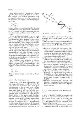
the refractive index of air is unity (in fact, it is Figure 21.19 AbbB refractometer.
1.000 27).
In practice for a solid sample we have to use a
piece with two non-parallel flat surfaces and this calibration also takes into account the glasdair
refraction which occurs when the rays leave
involves also measuring the angle between them. prism B.
This method can be used with the aid of a simple Although simple to use, this instrument suffers
table spectrometer. Liquid samples can be meas- from all the problems which complicate refractive
ured in this way with the use of a hollow prism, index measurements. It should be noted that
but it is a laborious method and requires a con-
siderable volume of the liquid. (1) In all optical materials the refractive index
Most refractometers instead make use of the
critical angle effect. When light passes from a varies markedly with wavelength in a non-
more dense to a less dense medium it may be linear fashion. Hence either nionochroniatic
sources or “compensating” devices must be
refracted (Figure 21.18(b)) but if the angle iz used. For high-accuracy work, monochro-
becomes so large that the ray cannot emerge from
the dense medium then the ray is totally internally matic sources are illvariably used.
reflected (Figure 21.18(c)). (2) The refractive index of most liquids also var-
The transition from refraction to internal ies markedly with temperature, and for accur-
reflection occurs sharply and the value of the ate work temperature control is essential.
angle of iz at which this occurs is called the “crit- (3) Since the refractive index varies with concen-
ical angle” (Figure 21.l&(d)). If we call that angle tration. difficulties may be encountered with
i, then concentrated solutions, especially of sugars,
which tend to become inhomogeneous under
m - 1 the effects of surface tension and gravity.
--
-
FZ~ sin ic (4) The range of refractive indices that can be
measured in critical-angle instruments is
Hence by determining ic we can find nl, if n2 is limited by the refractive index of the prism
known. A. Commercial instruments of this type are
available for measuring refractive indices up
to 1.74.
21.7.1.1 The Abbt; refiactoiwter (5) In visual instruments the light/dark field
The main parts of the Abbe refractometer which boundary presents such severe visual contrast
uses this principle are shown in Figure 21.19. The that it is sometimes difficult to align the
liquid under test is placed in the narrow space crosswires on it.
between prisms A and B. Light from a diffuse
monochromatic source (L), usually a sodium
lamp, enters prism A, and thus the liquid layer, 21.7.1.2 Mod$ied version of the Abbh refract-
at a wide variety of angles. Consequently light ometer
will enter prism B at a variety of angles which is
sharply limited by the critical angle. This light If plenty of liquid is available as a sample, the
then enters the telescope (T), and on moving the prism A of Figure 21.19 may be dispensed with
telescope around, a sharp division is seen at the and prism B simply dipped in the liquid. The
critical angle; one half of the field is bright and illuminating arrangements are as shown in Figure
the other is almost totally dark. The telescope is 21.20. Instruments of this kind are usually called
moved to align the cross-wires on the light/dark “dipping refractometers.”
boundary and the refractive index can be read off When readings are required in large numbers,
from a directly calibrated scale attached to it. This or continuous monitoring of a process is called