
Page 530 - Instrumentation Reference Book 3E
P. 530
Thermal imaging techniques 513
TuncJsten
lamp
Time Time
(a) (b)
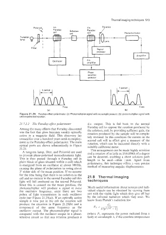
Figure 21.25 Faraday-effect polarimeter, (a) Photomultiplier signal with no sample present; (b) photomultiplier signal with
uncornDensated rotation
21.22.2 The FLwinlay-eflect polarimeter dc. output. This is €ed back to the second
Faraday cell to oppose the rotation produced by
Among tke many effects that Faraday discovered the solution, and, by providing sufficient pain, the
was the fact that glass becomes weakly optically rotation produced by the sample will he comple-
active in a magnetic field. This discovery lay tely restored. In this condition the current in che
unused for over a hundred years until its employ- second cell will in effect give a measure of the
ment in the Faraday-effect polarimeter. The main rotation, which can be indicated directly with a
optical parts are shown schematically in Figure suitably calibrated meter.
21.25. This arrangement can be made highly sensitive
A tungsten lamp, filter, and Polaroid are used and a rotation of as little as l/~~.~~Oth of a degree
to provide plane-po~ar~~ed ~onochro~~af Iight. can be detected, enabling a short solution path
ic
This is then passed &rough a Faraday cell (a length io be used-often imm. Apart from
plain block of glass situated within a coil) which polarimetry, this technique offers a veiy precise
is energized from an oscillator at about 380Hz, method of measuring angular displacements.
causing the plane of polarization to swing about
3" either side of the mean position. If we assume
for the time being that there is no solution in the 21.8 Thermal imaging
cell and no current in the second Faraday cell this
light will fall unaltered on the second Polaroid. techniques
Since this is crossed on the mean position, the
photomultiplier will produce a signal at twice Much usefd information about sources and iridi-
the oscillator frequency, since there are two vidual objects can be obtained by viewing them
pulses of light transmission in each oscillator not with the visible light which they give off but
cycle (see Figure 21.25(a)). If an optically active by the infrared radiation which they emit. We
sample is now put in the cell the rotation will know from Planck's radiation law
produce the situation in Figure 21.2S(b) and a
componelt of the same frequency as the
oscillator output. The photomultiplier signal is
compared with the ssciilator output in a phase- (where FA represents the po%:er radiated Erom a
sensitive circuit so that any rotation produces a body at wavelength A. 7'the absolute temperature