
Page 531 - Instrumentation Reference Book 3E
P. 531
514 Optical measurements
and CI and C2 are constants) that objects at the apparent. Thermal imaging can be used in medi-
temperature of our environment radiate signifi- cine to reveal variations of surface temperature
cantly, but we are normally unaware of this on a patient’s body and thus reveal failures of
because all that radiation is well out in the infra- circulation; it is of great military value since it
red spectrum. The peak wavelength emitted by will function in darkness, and has all manner of
objects at around 20°C (293 K) is about IOpm, applications in the engineering field.
whereas the human eye is only sensitive in the An excellent account of the technique is given
range 0.4-0.8 pm. By the use of an optical system by Lawson (1979) in Ekctronic Inicrging; Figure
sensitive to infrared radiation this radiation can 21.27 and Table 21.3 are based on this. Although
be studied, and since its intensity depends on the spectrum of a body around 300 K has its peak
the surface temperature of the objects concerned, at lOpm, the spectrum is quite broad. However,
the distribution of temperatures over an object or the atmosphere is effectively opaque from about
source can be made visible. It is possible to pick 5-8 pm, and above 13 pm, which means that in
out variations in surface temperature of less than practice the usable bands are 3-5 pm and
1 K in favorable circumstances, and so this teeh- 8-13pm. Although there is much more energy
nique is of great value; for example, it enables the available in the 8-13pm band (see Table 21.3)
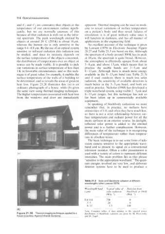
surface temperature of the walls of a building to and if used outdoors there is much less solar
be determined, and so reveals the areas of greatest radiation, the sensitivity of available detectors is
heat loss. Figure 21.26 illustrates this: (a) is an much better in the 3-5pm band, and both are
ordinary photograph of a house, while (b) gives used in practice. Nicholas (1968) has developed a
the same view using thermal imaging techniques. triple waveband system, using visible 2-5 pm and
The higher temperatures associated with heat loss 8-13pm ranges, but this technique has not so
from the windows and door are immediately far been taken up in commercially available
equipment.
In speaking of blackbody radiations we must
remember that, in practice, no surfaces have
emissivities of 1 .O, and often they have much less,
so there is not a strict relationship between sur-
face temperatures and radiant power for all the
many surfaces in an exterior source. In daylight,
reflected solar power is added to the emitted
power and is a further complication. However,
the main value of the technique is in recognizing
differences of temperature rather than tempera-
ture in absolute terms.
The basic technique is to use some form of tele-
vision camera sensitive to the appropriate wave-
band and to present its signal on a conventional
television monitor. Often a color presentation is
used with a variety of colors to represent different
intensities. The main problem lies in that phrase
“sensitive to the appropriate waveband.” The quan-
tum energies involved are very low, and elaborate
detector systems have to be used to produce a
Table 21.3 Solar and blackbody radiation at different
wavelengths (after Lawson 1979)
.___~
Wuvelength hand Tvpicul value o/ Emission ,froni
( Pm) soh radiation hlackhoclv at 300 K
(Wm ?) (Wm-?)
-~ ~~
.~
0.4-0.8 750 0
35 24 6
8-13 1.5 140
-.
(b) Note: Complete tables of data relating to the spectral power
Figure 21.26 Thermal imaging techniques applied to a distribution of blackbody radiators are given by M. Pivovonsky
house (courtesy Agema Infrared Systems). and M. Nagel.