
Page 528 - Instrumentation Reference Book 3E
P. 528
Measurement of optical properties 511
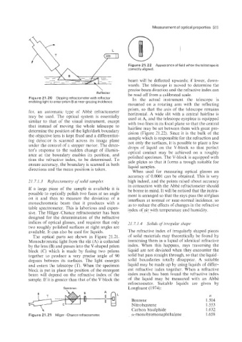
Figure 21.22 Appearance of field when thetelescope is
correctly aligned.
beam will be deflected upwards; if lower, down-
wards. The telescope is moved to determine the
precise beam direction and the refractive index can
Reflector be read off from a calibrated scale.
Figure 21.20 Dipping refractometer with reflector In the actual instrument the telescope is
enabling light to enter prism B at near-grazing incidence,
mounted on a rotating arm with the reflecting
prism, so that the axis of the telescope remains
for, an automatic type of AbbC refractometer horizontal. A wide slit with a central hairline is
may be used. The optical system is essentially used at A, and the telescope eyepiece is equipped
similar to that of the visual instrument, except with two lines in its focal plane so that the central
that instead of moving the whole telescope to hairline may be set between them with great pre-
determine the position of the light/dark boundary cision (Figure 21.22). Since it is the bulk of the
the objective lens is kept fixed and a differentiat- sample which is responsible for the refraction and
ing detector is scanned across its image plane not only the surfaces; it is possible to place a few
under the control of a stepper motor. The detec- drops of iiquid on the Q-block so that perfect
tor’s response to the sudden change of illumin- optical contact may be achieved on a roughly
ance ai the boundary enables its position. and polished specimen. The V-block is equipped with
thus the refractive index, to be determined. To side plates SO that it fernis a trough suitab!e for
ensure accuracy. the boundary is scanned in both liquid samples.
directioiis and the mean position is taken. When used for measuring optical glasses an
accuracy of 0.0001 can be obtained. This is very
21.7.1.3 Rej?artoi?zetry of solid samples high indeed, and the points raised about accuracy
in connection with the AbbC refractometer should
If a large piece of the sample is available it is be borne in mind. It will be noticed that the instru-
possible to optically polish two faces at an angle ment is arranged so that the rays pass the air/glass
on it and then to measure the deviation of a interfaces at nomial or near-noimal incidence, so
monochromatic beam that it produces with a as to reduce the effects of changes in the refractive
table spectrometer. This is laborious and expen- index of air with terr-perature and humidity.
sive. The Wilger-Chance refractometer has been
designed for the determination of the refractive
indices of optical glasses, and requires that only 21.7.1.4 Soli& of irregzcka shape
two roughly polished surfaces at right angles are
available. It can also be used for liquids. The refractive index of irregularly shaped pieces
The optical parts are shown in Figure 21.21. of solid materials may theoretically be found by
Monochromatic light from the slit (A} is collected immersing them in a liquid of identical refractive
by the lens (B) and passes into the V-shaped prism index. When this happens, rays traversing the
block (C) which is made by fusing two prisms liquid are not deviated when they encounter the
together to produce a very precise angle of 90 solid but pass straight through, so that the liquid-
degrees between its surfaces. The light emerges solid boundaries totally disappear. A suitable
and enters .the telescope (T). When the specimen liquid may be made up by using liquids of differ-
block is put in place the pasition of the emergent ent refractive index together. When a refractive
beam will depend on the refractive index of the index match has been found the refractive index
sample. If it is greater than that of the V block the of the liquid may be measured with an AbbC
refractometer. Suitable liquids are given by
Specimen Longhurst (1 974):
?I
Benzene 1.504
Nitrobenzene 1.553
h Carbon bisulphide 1.632
Fig we 21.21 Hilger-Chance refractometer a-monobromonaphthalene 1.658