
Page 198 - Integrated Wireless Propagation Models
P. 198
176 C h a p t e r T h r e e
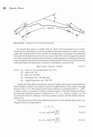
FIGURE 3.4.2.1 Geometry of a transhorizon radio path.
If a terrain data map is available, then the above listed parameters can be deter
mined for any particular path, and the prediction technique operates in a point-to-point
mode. If the terrain profile is not available, the program gives techniques for estimating
these path-related parameters for use in an area model. The terrain irregularity param
eter �h is a roughness indicator that is related to another parameter �h(d), the interdecile
range of heights, estimated at fixed distances along the path. The value of �h(d) increases
with path length. For long paths, it reaches an asymptotic value given by
�h(d) = M [ - 0.8 exp (-0.02d)] (3.4.2.1)
1
where for water or very smooth plains, �h = 0-5;
for plains, �h "' 30;
for hills, �h "' 80-150;
for mountains, �h "' 150-300; and
for rugged mountains, �h "' 300-700.
Longley and Rice define the effective antenna heights with respect to the dominant
reflecting plane similar to the effective antenna height defined in Lee model's formula
shown in Sec. 3.1.2.3. The smooth earth horizon distance d is determined by d L = �17he
L
in metric units as a function of effective antenna height h The total distance between
,
the antennas and their respective horizons is d = d b + d m where d b and d m are the
L
L
L
L
L
'
smooth-earth horizon distances of the base station antenna and the mobile antenna,
respectively.
In the area-to-area model, the statistical estimations of the relevant parameters over
irregular terrain are expressed as
(3.4.2.2)
d b = d ub exp[-0.07 J¥J (3.4.2.3)
L
d m = d �.sm exp[-0.07 J¥J (3.4.2.4)
L