
Page 54 - Integrated Wireless Propagation Models
P. 54
32 C h a p t e r O n e
For the case when the first medium is free space and the second medium has a rela
tive permittivity r, Eq. (1.9.1.2.1) can be expressed as
. �E, - 1 1
vE; - 1 vE, + 1
sm(�) = r::21 = � (1.9.1.2.2)
Note that the Brewster angle occurs only for vertical polarization, v i.e., E-field is in the
plane of incidence, as shown in Fig. 1.9.1.1.2(a).
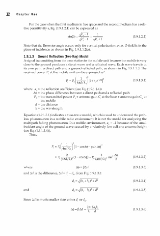
1.9.1.3 Ground Reflection (Two-Ray) Model
A signal transmitting from the base station to the mobile unit because the mobile is very
close to the ground produces a direct wave and a reflected wave. Each wave travels in
1
.
its own path, a direct path and a ground-reflected path, as shown in Fig. . 9 1 . 1 . 3. The
received power P, at the mobile unit can be expressed as4
.
(1. 9 . 3.1)
1
where a = the reflection coefficient (see Eq. (1.9.1. 1 . 4))
v
�<I> = the phase difference between a direct path and a reflected path
P = the transmitted power P, + antenna gain G, at the base + antenna gain G"' at
0
the mobile
d = the distance
'A = the wavelength
1
Equation (1.9. . 3.1) indicates a two-wave model, which is used to understand the path
loss phenomenon in a mobile radio environment. It is not the model for analyzing the
multipath fading phenomenon. In a mobile environment, a" = -1 because of the small
incident angle of the ground wave caused by a relatively low cell-site antenna height
(see Eq. (1.9 1 . 1 . 4)).
.
Thus,
P, = P( � . .J1 1 - cosM- jsin�qf
/ I
0
4n
2 4 . M
= P o ( 1 - cos�<j> ) - - P o 2 (1.9.1.3.2)
(4nd /W (4nd /1.,) sm 2
where (1.9.1.3.3)
and t.d is the difference, t.d = d1 - d , from Fig. 1 . 9.1.3.1:
0
(1.9.1.3.4)
and (1.9.1.3.5)
Since �d is much smaller than either d1 or d ,
0
(1. 9 .1.3.6)