Page 53 - Integrated Wireless Propagation Models
P. 53

I n t r o d u c t i o n   t o   M o d e l i n g   M o b i l e   S i g n a l s   i n   W  i r e l e s s   C o m  m  u n i c a t i o n s    31


                                                                            + E ­
                                                                               wave
                                                                        T� ®H


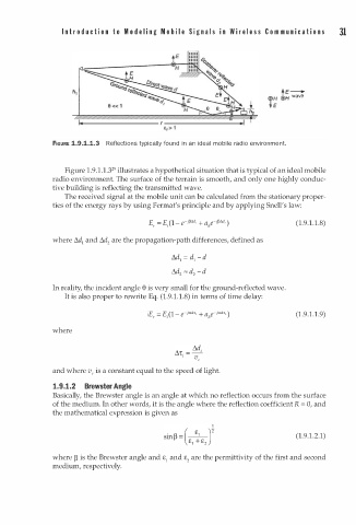
               FIGURE 1.9.1.1.3  Reflections typically found i n   an ideal mobile radio environment.


                               2
                  Figure  . 9 . 1 . 1 . 3 9 illustrates a hypothetical situation that is typical of an ideal mobile
                        1
               radio environment. The surface of the terrain is smooth, and only one highly conduc­
               tive building is reflecting the transmitted wave.
                  The received signal at the mobile unit can be calculated from the stationary proper­
               ties of the energy rays by using Fermat's principle and by applying Snell's law:

                                                                                   1
                                                                                (1. 9  . 1 .8)
                                                                                   .
               where t1d1 and t1d are the propagation-path differences, defined as
                              2
                                               t1d l  =  d l  - d
                                               t1d 2  "" d - d
                                                    2
               In reality, the incident angle e is very small for the ground-reflected wave.
                                               1
                  It is also proper to rewrite Eq. (1.9. . 1 .8) in terms of time delay:
                                                                                   .
                                                                                   1
                                                                                (1. 9  . 1 .  9)
               where


               and where v,  is a constant equal to the speed of light.

               1.9.1.2  Brewster Angle
               Basically, the Brewster angle is an angle at which no reflection occurs from the surface
               of the medium. In other words, it is the angle where the reflection coefficient R = 0, and
               the mathematical expression is given as


                                                                                (1.9.1.2.1)


               where � is the Brewster angle and £ 1  and £ are the permittivity of the first and second
                                                   2
               medium, respectively.
   48   49   50   51   52   53   54   55   56   57   58