
Page 98 - Integrated Wireless Propagation Models
P. 98
76 C h a p t e r T w o
Base Station Receiver
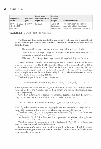
Frequency Distance Effective Antenna Antenna
(MHz) (km) Height (m) Height Correction Factors
a
200, 453, 922, 1-1000 30-1000 Typical of Suburb n , open and isolated
l
a
1310, 1430, land mobile mount i n , ro l i n g hills, sloping
m
and 1920 applications terr i n , and i xed land-sea paths
a
TABLE 2.12.1.1 Okumura-Hata Model Parameters
The Okumura-Hata model divides the area being investigated into a series of clut
ter and terrain types, namely, open, suburban, and urban. Definitions of these areas are
described here:
• Open area: Open space, such as farmland, rice fields, and open fields
• Suburban area: A village or highway scattered with trees and houses, such as
residential areas and small towns
• Urban area: A built-up city or large town with large buildings and houses
The Okumura-Hata model uses the free space loss as baseline and derives the refer
ence curves, as shown in Fig. 2.12. . 1 for a fixed base station antenna height of 200 m
1
and a mobile antenna height of 3 m. Based on the frequencies and distance, the basic
median attention (path loss), Amu (f, d), can be found on the curve. The base station
antenna height correction factor is shown in Fig. 2.12.1.2, and the mobile antenna height
correction factor is shown in Fig. 2.12.1.3.
The baseline predicted value is expressed as
.
Path Loss (median attenuation) (dB) = L + A ,"' ( f , d) + hb + h .,. (2.12 1 . 1 )
1
o
o
i
where L i s the free space loss and A"'" s a function f distance f frequency, derived
1
from Fig. 2.12.1.1, and hb and h.,. are the base station and the mobile station antenna
height, respectively.
Correction factors have to account for antennas heights other than the reference
heights. The basic formulation of the technique can be expressed as
Path Loss (median attenuation) (dB) = L + A""' (f, d) + hb + h,, + h .,. + h,, (2.12.1.2)
1
where h,, is the base station antenna height gain factor as a function of range and h,, is
the mobile (receiver) antenna height gain factor as a function of frequency.
The dependency of hb on propagation loss is shown in Fig. 2.12.1.2. It shows that
path loss increases as the antenna height decreases.
As shown in Fig. 2.12.1.3, the correction is presented as relative height gain to a
mobile station 3 i n height in an urban area over quasi-smooth terrain.
m
.
The dependence of fc on propagation loss is shown in Fig. 2.12 1 . 4. It shows that
path loss increases as the frequency increases.
More correction factors are also provided in graphical form for rolling hilly terrain,
isolated mountain, general sloping terrain, and mixed land-sea path, and can be added
or subtracted as appropriate.